
A method for obtaining aerosol particle size distributions

Active Publication Date: 2016-12-22
PARTICLE MEASURING SYST
View PDF3 Cites 1 Cited by
  • Summary
  • Abstract
  • Description
  • Claims
  • Application Information

AI Technical Summary

Benefits of technology

The invention provides a way to set up an SMPS to measure particle sizes from 3 nm to 4,000 nm without needing to change the DMA chamber or increase the voltage. This allows for more accurate and reliable measurements.

Problems solved by technology

All heavy industries involving processes emitting fumes have potential problems with the emission of aerosol particles.
There is also concern amongst consumer companies that use of enzymes in washing powders, powder coatings and fibres used in disposable nappies and other products could cause problems.
In addition, the US EPA is becoming increasingly concerned about gasoline engine emissions.
Nano-particles and nano-objects are known to produce toxic effects.
Early studies with PTFE (polytetrafluoroethylene) particles around 20 nm in diameter showed that airborne concentrations of a supposedly inert insoluble material lower than 50 μg / m3 could be fatal to rats.
Real particles in the air often have complicated shapes.
The differences in shape and density cause considerable confusion in defining particle size.
However, it is not a true geometric size because non-spherical particles usually have a lower terminal settling velocity than spherical particles.
The investigation and monitoring of aerosol particles in the atmosphere has been hampered by a shortage of instruments which can measure in the wide particle size range but which are sufficiently inexpensive, robust and convenient to be used on a widespread basis.
In this wide range, the mobility of the particles varies over several orders of magnitude and, in practice, it is extremely difficult to measure such wide ranges of particle sizes using a single DMA device.
However, the device of U.S. Pat. No. 7,140,266 suffers from several potential drawbacks.
Firstly, the device requires a large pump for the impactor which means that the device would be difficult to build as a portable instrument.
Secondly, a cascade impactor classifies particles according to their aerodynamic diameters which may differ from their diffusion diameters, and consequently, the particle size distributions obtained by combining the results obtained from the impactor and the DMA may be rather difficult to interpret.
The analyzer disclosed in US 20060266132 enables the measurable particle size range to be extended but a disadvantage is that the dimensions of the apparatus are necessarily increased, thereby mitigating against miniaturization and the construction of portable versions of the instrument.
Differential mobility analyzers working on the above principles can be used very effectively to select particles of up to about 500 nm but, for larger particle sizes, problems do arise.
In order to select particles of larger sizes, higher electrode voltages will be required and this places certain practical limits on the DMA.
If the voltage is too high, corona discharges (or even complete electrical field breakdown) are likely to occur between the electrodes.
This would be a particular problem for DMA devices with relatively narrow gaps between the electrodes (for example in miniaturized or portable devices).
An alternative to increasing the electrode voltage is to increase the length of the DMA chamber but this would lead to DMA chambers of impractical length and would further militate against miniaturization and the construction of portable hand-held DMA devices.
However, reducing the flow rate will also allow more time for the particles to undergo random movement by diffusion thereby leading to poorer resolution.

Method used


Image

  • A method for obtaining aerosol particle size distributions
  • A method for obtaining aerosol particle size distributions
  • A method for obtaining aerosol particle size distributions

Examples


Embodiment Construction

[0050]The invention will now be illustrated in greater detail by reference to the specific embodiments described below and illustrated in the accompanying drawings FIGS. 1 to 9.

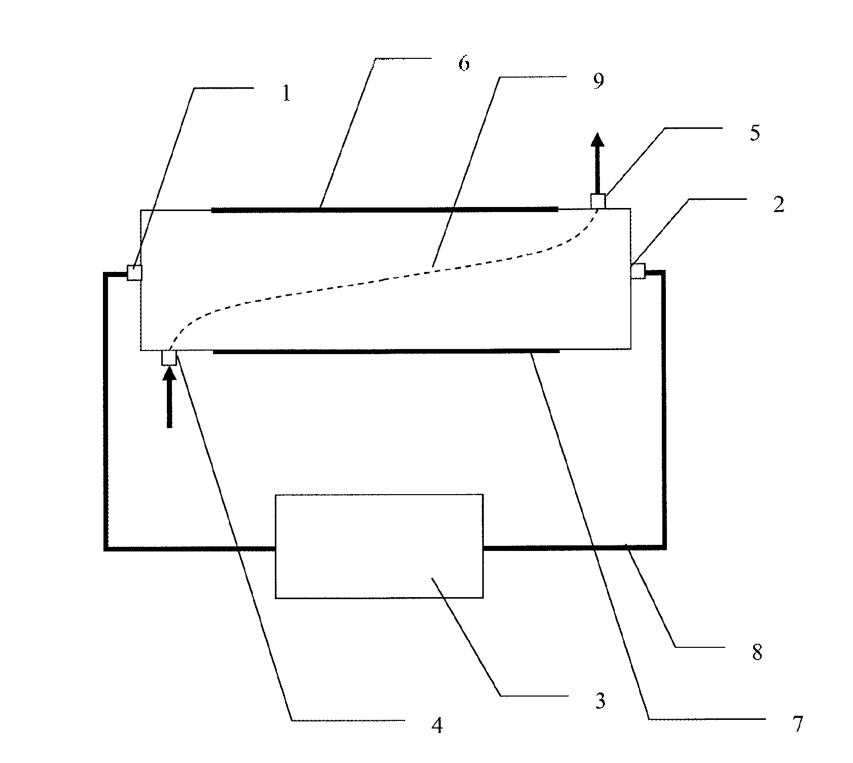
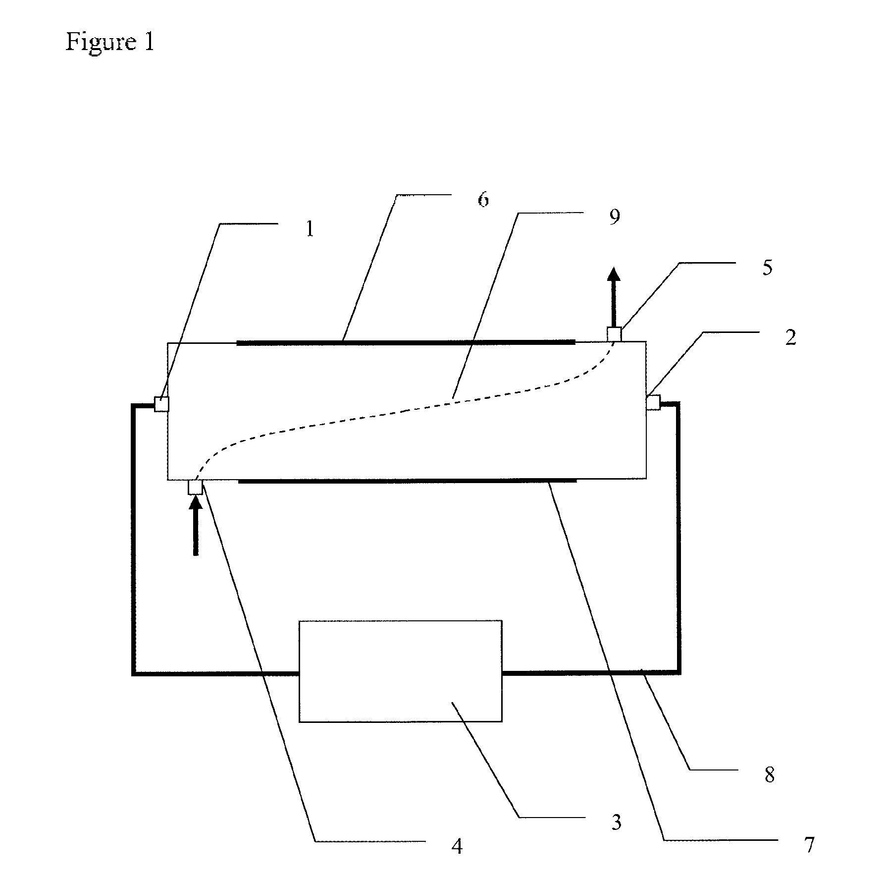
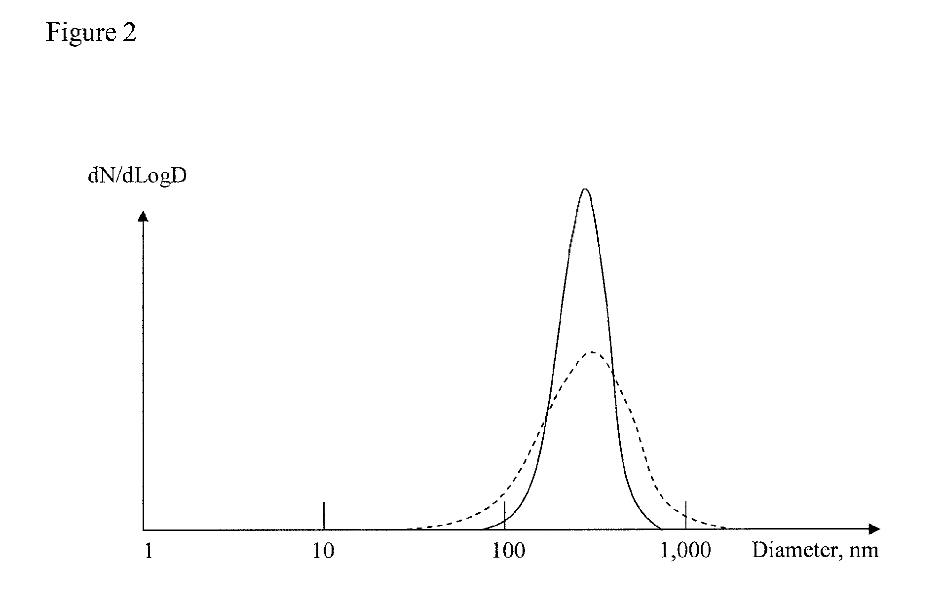
[0051]FIG. 1 is a schematic side sectional view of a known type of a planar DMA unit used in SMPS apparatus and functions in the manner described above in the introduction section of this application. A schematic view of aerosol particle size distributions obtained at various sheath flow rates is shown in FIG. 2.

[0052]According to the invention, the apparatus shown in FIG. 1 (and other DMA / SMPS apparatuses) can be obtained with two different sheath flow rates changing at a transition size Dt. Initially, a part of the size distribution is recorded at a sheath flow rate of Qsh1, see FIG. 3. The measurements extend from the lowest size to point A, which corresponds to the transition size Dt. At this point, the scan is stopped and the sheath flow rate is changed from Qsh1 to a smaller value Qsh2. At the smaller s...


PUM


Abstract

The invention provides a method for obtaining aerosol particle size distributions with a scanning mobility particle sizer (SMPS) device comprising a differential mobility analyzer (DMA); which method comprises the stages:(i) collecting a first data set of particle concentrations vs. size for a size range from a predetermined minimal size Dmin to an intermediate size Dt by varying a voltage applied to a DMA column of an SMPS from Vmin to Vt1 at a first sheath flow rate Qsh1;(ii) changing the sheath flow rate from the first sheath flow rate Qsh1 to a second sheath flow rate Qsh2;(iii) collecting a second data set of particle concentrations vs. size for a size range from the intermediate size Dt to a predetermined maximum size Dmax by varying the voltage applied to the DMA column of the SMPS from Vt2 to Vmax at the second sheath flow rate Qsh2;(iv) convolving the first data set from stage (i) using an apparatus function of the DMA and the sheath flow rates Qsh1 and Qsh2 in stage (ii);(v) combining the convolved data set from stage (iv) with the second data set from stage (iii) to form a merged data set corresponding to the size distribution from Dmin to Dmax; and(vi) deconvolving the merged data set to provide a size distribution for the full size range Dmin to Dmax.Also provided are a DMA, SMPS or Fast Mobility Particle Sizer (FMPS) apparatus set up to perform the method.

Description

[0001]This invention relates to a method for obtaining aerosol particle size distributions. More particularly, the invention relates to a method that enables selection of monodisperse aerosol particles from a polydisperse particle ensemble in a wider particle size range.BACKGROUND OF THE INVENTION[0002]There is currently a great deal of concern about the health effects of nano-particles and micro-particles emitted unintentionally into the air. For example, a considerable increase in respiratory illness and allergies in the UK in recent years has been associated in part with particles emitted by diesel engines and other combustion processes. Whilst the main focus has been on diesel emissions, attention is turning to other potential sources such as power generation using fossil fuels, incineration, nuclear power generation and aircraft emissions. All heavy industries involving processes emitting fumes have potential problems with the emission of aerosol particles. Such processes inclu...

Claims


Application Information

Patent Timeline
IPC IPC(8): G01N27/62G01N15/02G01N15/10
CPCG01N27/622G01N2015/1087G01N15/0266G01N15/10G01N2015/0046G01N1/2202G01N15/0255G01N2001/2223G01N2015/0288G01N2015/0038G01N27/62G01N15/02G01N2015/1029
Inventor GORBUNOV, BORIS ZACHAR
Owner PARTICLE MEASURING SYST
Learn More