
Calibration network for a phased array antenna

Active Publication Date: 2016-12-29
ELTA SYST LTD
View PDF0 Cites 20 Cited by
  • Summary
  • Abstract
  • Description
  • Claims
  • Application Information

AI Technical Summary

Benefits of technology

The patent text describes a need for a calibration network system and method for array antennas that are simpler and more compact. The invention provides a way to connect multiple antenna elements to a single calibration line, which simplifies the process and reduces complexity. The technical effect is a more efficient and compact calibration network for array antennas.

Problems solved by technology

During use, performance of the antennas may deteriorate over time since one or more antenna elements may get out of calibration.
In addition, failed T / R modules must be replaced.
Replacement of a failed T / R module during antenna maintenance is usually a routine procedure, however, since the replaced T / R modules inevitably have slightly different properties to the original antenna elements, the original offsets will not compensate for slight differences in the phase and gain characteristics of the phase shifters and amplifiers used to feed steering signals to the corresponding antenna elements.

Method used


Image

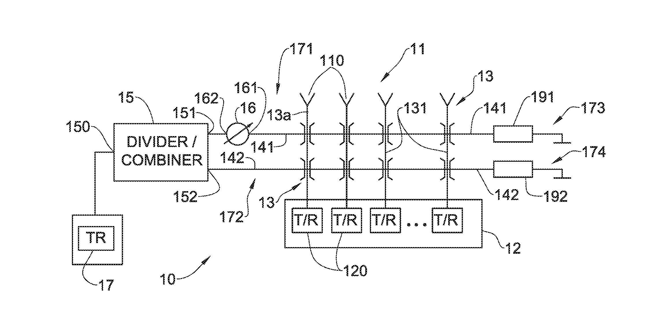
  • Calibration network for a phased array antenna
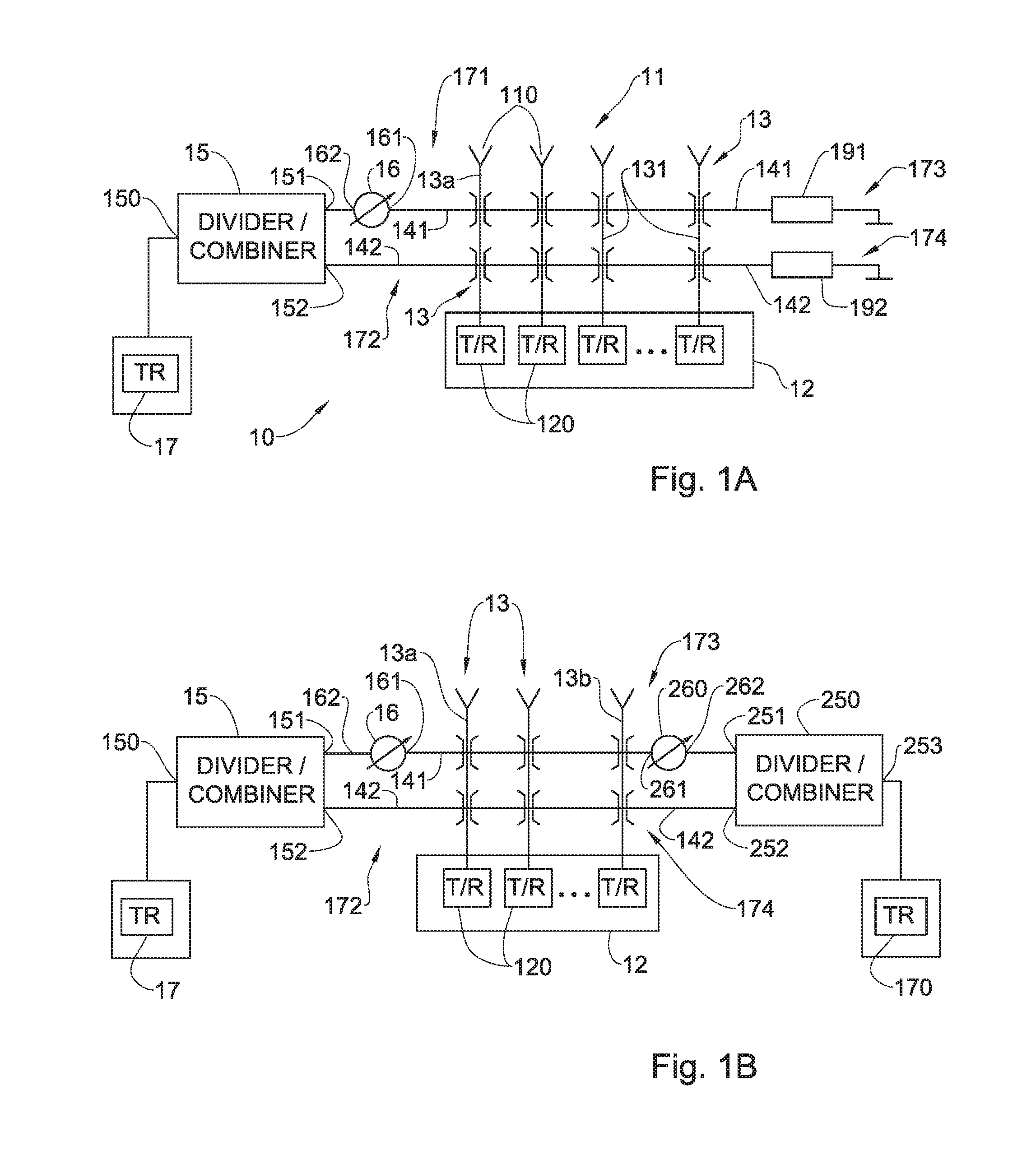
  • Calibration network for a phased array antenna
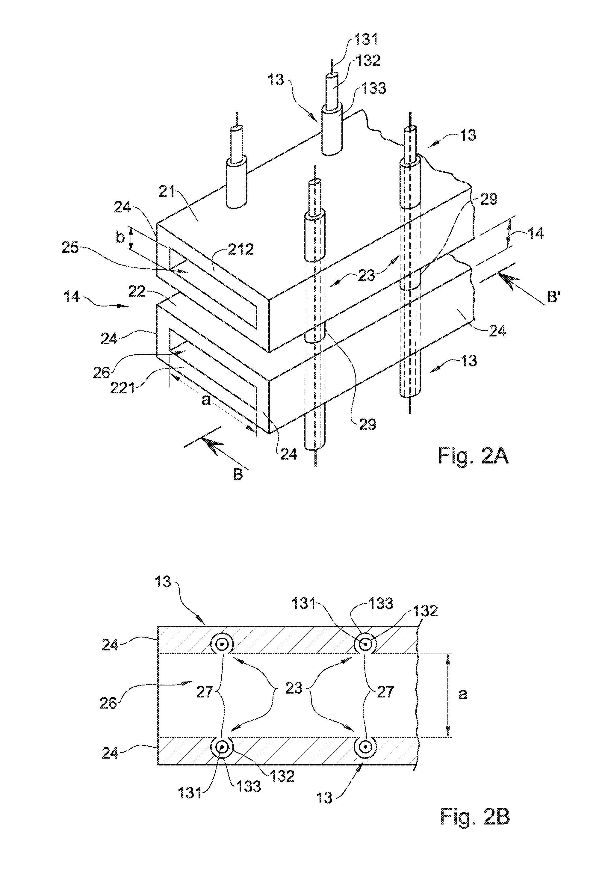
  • Calibration network for a phased array antenna

Examples


Embodiment Construction

[0075]The principles of the method and system according to embodiments of the present invention may be better understood with reference to the drawings and the accompanying description, wherein like reference numerals have been used throughout to designate identical elements. It is to be understood that these drawings, which are not necessarily to scale, are given for illustrative purposes only and are not intended to limit the scope of the invention. For example, the dimensions of some of the elements in the figures may be exaggerated relative to other elements to help improve understanding of various embodiments. In addition, the description and drawings do not necessarily require the order illustrated. It will be further appreciated that certain actions and / or steps may be described or depicted in a particular order of occurrence while those skilled in the art will understand that such specificity with respect to sequence is not actually required.

[0076]It should be noted that the...


PUM


Abstract

A calibration network system for an array antenna and method for calibrating of the array antenna are described. The system includes a pair of rectangular waveguides stacked in parallel relation to each other and spaced apart at a distance of a quarter of an operating wavelength. The rectangular waveguides includes through-holes extending through a side-wall of the stacked rectangular waveguides from a bottom of a lower waveguide to a top of an upper waveguide to accommodate coaxial transmission lines. The side-wall has openings between the through-holes and an interior region of the rectangular waveguides in order to provide coupling of the coaxial transmission lines into the pair of rectangular waveguides. The system includes 90 degree phase shifter coupled to the upper rectangular waveguide, and a power divider / combiner coupled to a reference T / R Module, to the 90 degree phase shifter and to the lower rectangular waveguide.

Description

CROSS-REFERENCE TO RELATED APPLICATIONS[0001]This application claims priority to Israel Patent Application No. 239596 filed on 23 Jun. 2015, the disclosure of which is incorporated herein, in its entirety, by this reference.TECHNICAL FIELD[0002]Embodiments of the invention relate to phased array antennas and, in particular, to calibration of phased array antennas.BACKGROUND[0003]A phased array antenna includes an array of antenna elements adapted to produce a plurality of collimated and differently directed beams of radio frequency (RF) energy. Beams are formed by weighing the amplitude and shifting the phase of the signal emitted from each radiating element, to provide constructive / destructive interference so as to steer the beams in the desired direction.[0004]Each element in the phased array, or a group of elements, is driven by a transmit / receive (T / R) module which includes a controllable attenuator (or amplifier) and a controllable phase-shifter adapted for controlling the ampl...

Claims


Application Information

Patent Timeline
IPC IPC(8): H04B17/12H01Q3/26H04B17/21H04B1/40H01Q3/30
CPCH04B17/12H04B1/40H04B7/0617H04B17/21H01Q3/267H01Q3/30H01Q3/00
Inventor FEIGIN, YURI
Owner ELTA SYST LTD
Learn More