
DC-balanced, transition-controlled, scalable encoding method and apparatus for multi-level signaling

a multi-level signaling and scalable technology, applied in the direction of synchronous/start-stop systems, digital transmission, baseband system details, etc., can solve the problems of dielectric loss and reflection becoming more and more of a problem, the improvement of data transmission medium (channel) is relatively slow, and the effect of compact implementation

Active Publication Date: 2021-10-12
SEOUL NAT UNIV R&DB FOUND
View PDF6 Cites 0 Cited by
  • Summary
  • Abstract
  • Description
  • Claims
  • Application Information

AI Technical Summary

Benefits of technology

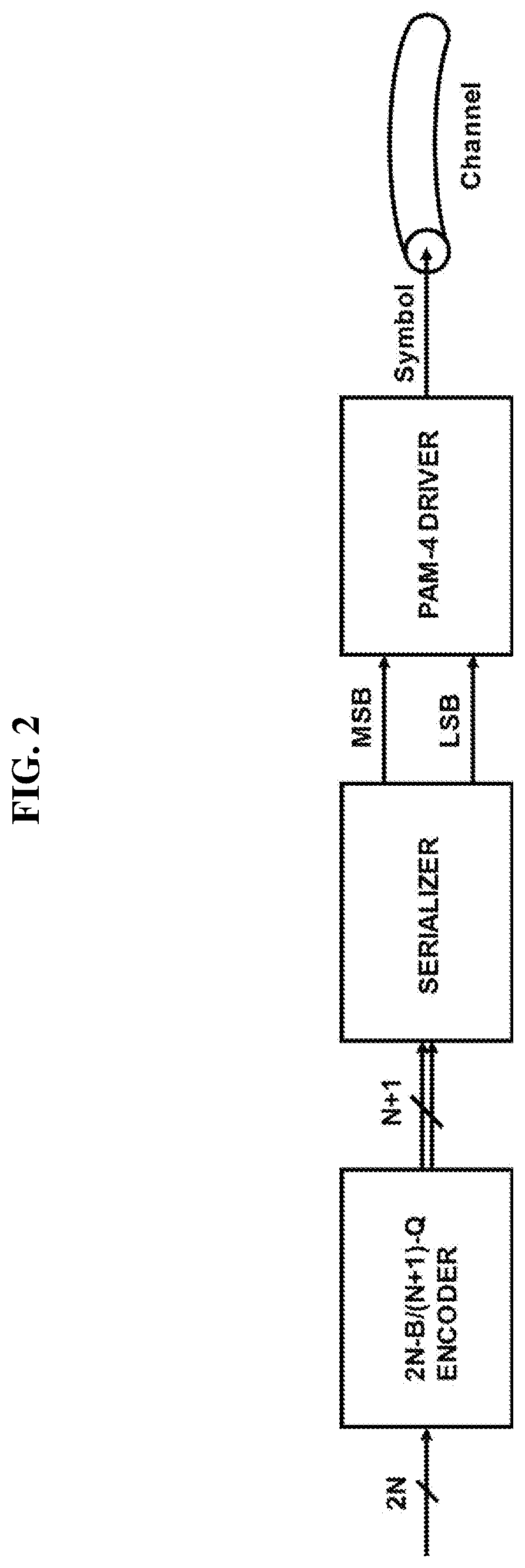
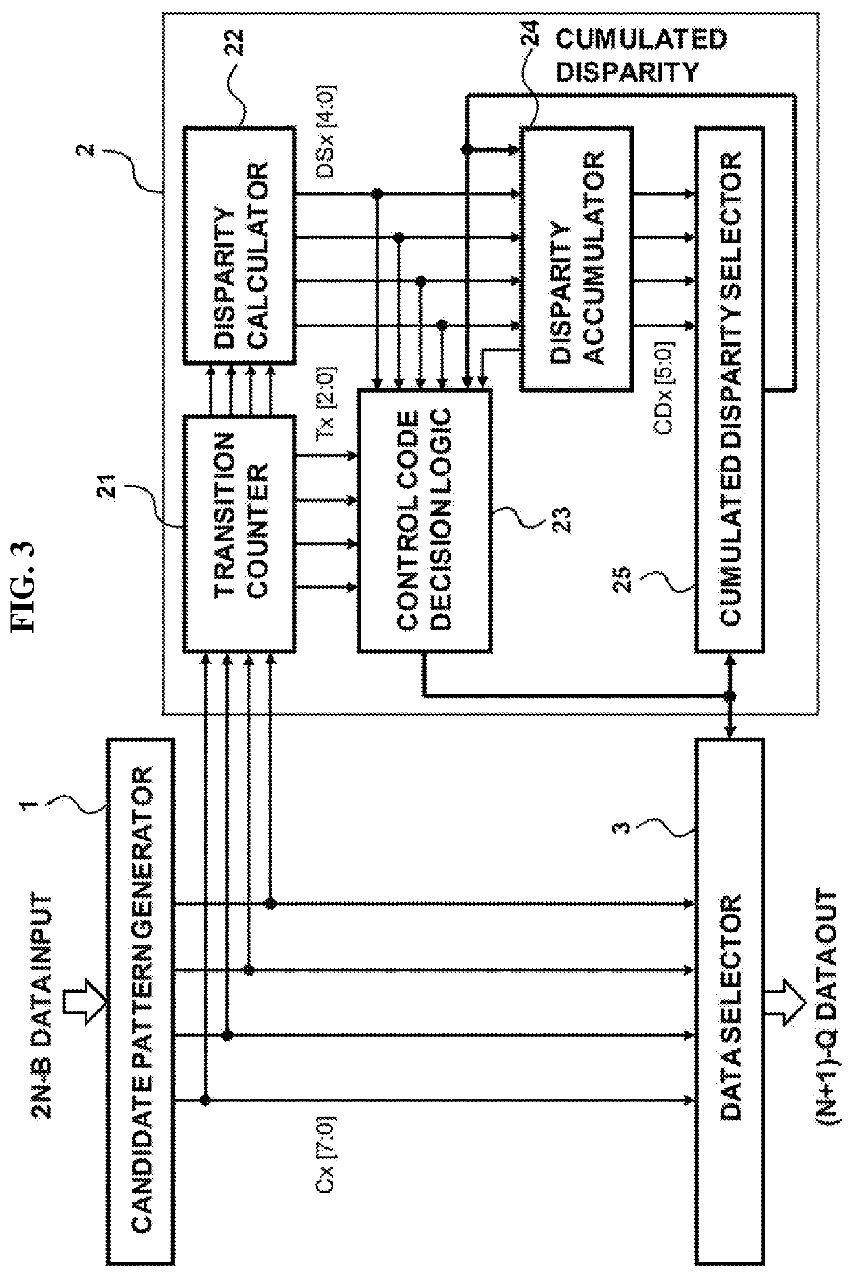
The present invention provides an encoding apparatus and method that can reduce coding overhead for DC balancing as the input data length increases. The output data pattern is selected among the candidate patterns by referring to the cumulated disparity value to achieve DC balance. The CDR circuit of the receiver can more accurately and rapidly recovering a data sampling clock phase with more zero-crossing transitions. The invention has a scalability characteristic and can be applied to input data having an arbitrary 2N-B length. The coding overhead is remarkably reduced in the case of values of N>4. The invention consists of only a combinational logic and a final data pattern selector, so the implementation is simple and compact.

Problems solved by technology

On the other hand, compared to the increase rate of the data rate needs required in an application, the improvement in a data transmission medium (channel) is relatively slow.
Therefore, deterioration in signal integrity caused by frequency-dependent distortion such as the skin effect, and dielectric loss and reflection has become more and more of a problem.
In the case of the NRZ, when the number of 1's and the number of 0's are not balanced, deterioration in signal integrity caused by drift of the DC level may occur.
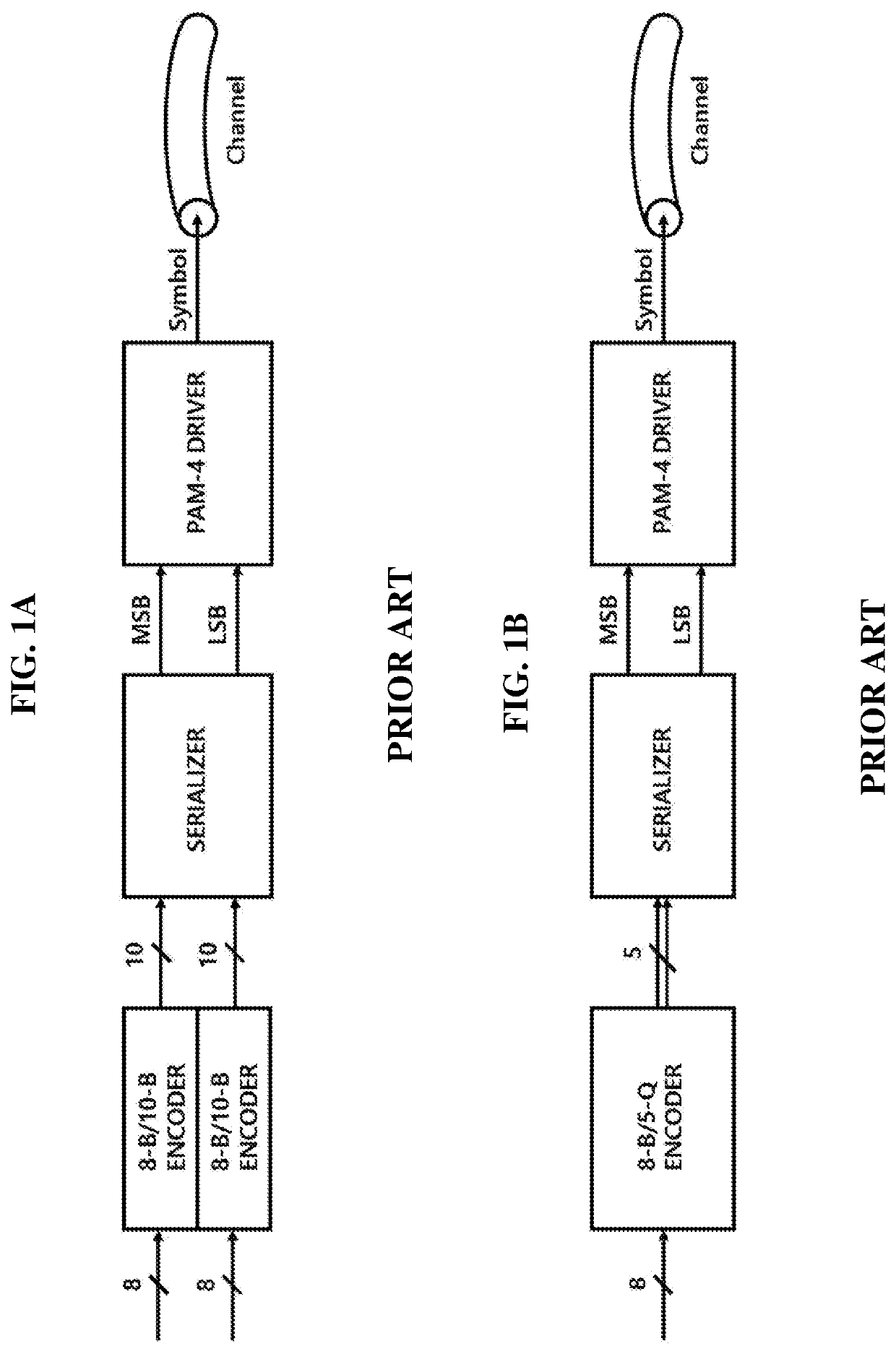
However, when PAM-4 DC balancing based on the 8-B / 10-B encoder is implemented, coding overhead of 25% occurs and the load is imposed on the data bandwidth.
However, there is also a constraint that the 8-B / 10-B encoder is impossible to be applied to the data length other than that corresponding to Byte×2 (16-B).
However, due to the nature of mapping based on a look-up table, in the same manner as the 8-B / 10-B encoder, application to an data input corresponding to the data length other than Byte (8-B) is impossible, and coding overhead of 25% occurs.
This may be disadvantageous to increase the data rate.

Method used


Image

  • DC-balanced, transition-controlled, scalable encoding method and apparatus for multi-level signaling
  • DC-balanced, transition-controlled, scalable encoding method and apparatus for multi-level signaling
  • DC-balanced, transition-controlled, scalable encoding method and apparatus for multi-level signaling

Examples


Embodiment Construction

[0034]The present invention relates to an encoding method and apparatus, wherein a data sequence having an arbitrary length is used as an input and an output symbol having a DC-balanced characteristic in addition to a transition-controlled characteristic is generated. The encoding method may be executed in a transmitter, and the encoding apparatus may be included in the transmitter. A decoding method in a dual relationship with the encoding method according to the present invention may be executed in a receiver, and a decoding apparatus in a dual relationship with the encoding apparatus may be included in the receiver.

[0035]Although the scope of the present invention is not limited to PAM-4, for clear description, PAM-4 among types of multi-level signaling will be described below as an example.

[0036]FIG. 2 is a block diagram of a transmitter chip that performs PAM-4 DC balancing according to an embodiment of the present invention. In PAM-4 signaling, conversion into a 1-Q symbol is ...


PUM


Abstract

The present invention relates to an encoding apparatus for multi-level signaling, the encoding apparatus including: a candidate pattern generator (1) generating a set of candidate patterns from input data by using symbol-based inversion; a controller (2) generating a cumulated disparity value that is a result of calculating disparity indicating a degree to which transmission data up to previous transmission deviates from DC balance, storing the cumulated disparity value, and determining a transmission control code by using the cumulated disparity value and a set of disparity values that is a result of calculating disparity indicating a degree to which each of the candidate patterns deviates from DC balance; and a data selector (3) selecting one candidate pattern from the set of the candidate patterns as data to be transmitted, according to the determined transmission control code.

Description

BACKGROUND OF THE INVENTIONField of the Invention[0001]The present invention relates to an encoding method and apparatus for multi-level signaling.Description of the Related Art[0002]In a wireline architecture performing optical or electrical data transmission for Internet networking, an increase in data rate is continuously required. In order to satisfy this requirement, an optical / electrical link design also continues to technologically advance through an increase in an operating speed and the number of pin ports of a system.[0003]On the other hand, compared to the increase rate of the data rate needs required in an application, the improvement in a data transmission medium (channel) is relatively slow. Therefore, deterioration in signal integrity caused by frequency-dependent distortion such as the skin effect, and dielectric loss and reflection has become more and more of a problem. As the channel loss becomes a problem due to high Nyquist frequency, multi-level signaling throug...

Claims


Application Information

Patent Timeline
Patent Type & Authority Patents(United States)
IPC IPC(8): H04L25/49H03M5/14H04L25/02
CPCH04L25/4917H03M5/145H04L25/0272H04L25/4908H04L25/4919
Inventor LEE, WOONGHEEJEONG, DEOG-KYOON
Owner SEOUL NAT UNIV R&DB FOUND
Learn More