
Computer-assisted planning and execution system

a computer-aided planning and execution system technology, applied in the field of surgery, can solve problems such as inability to validate the optimization method, inability to provide custom features for reducing problems, and inability to accurately place guides, so as to improve outcomes, reduce accompanying morbidity, and increase the robustness of conventional cas paradigms.

Active Publication Date: 2017-01-05
THE JOHN HOPKINS UNIV SCHOOL OF MEDICINE
View PDF1 Cites 7 Cited by
  • Summary
  • Abstract
  • Description
  • Claims
  • Application Information

AI Technical Summary

Benefits of technology

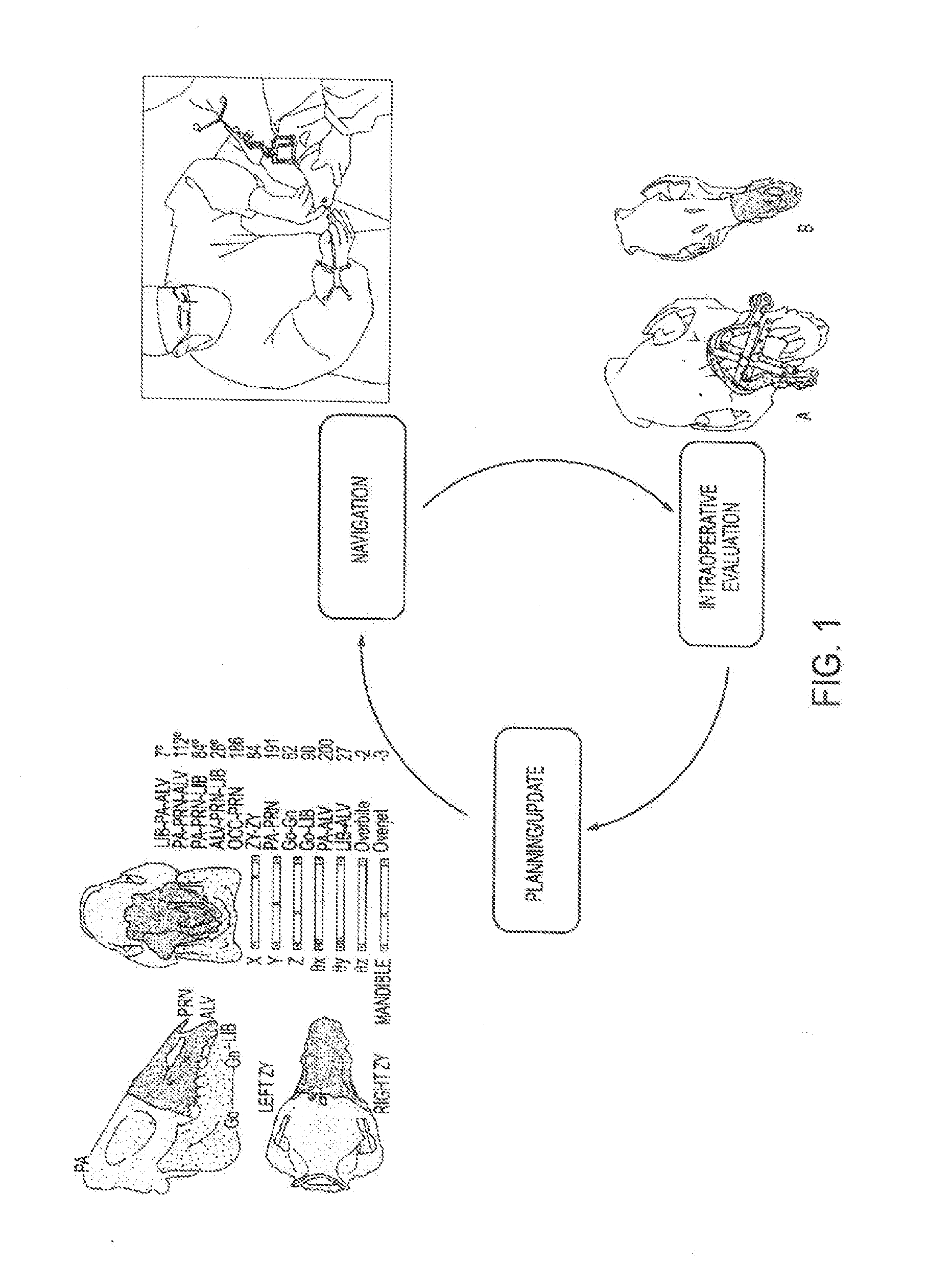
The invention provides a surgical system that is more robust than conventional CAS methods, which means it can better handle situations that might occur during surgery. This is especially important in total face transplantation, where the operation can take very long. By using the new system, surgeons can plan and navigate the surgery more accurately and quickly, which can improve outcomes and decrease complications.

Problems solved by technology

Face-jaw-teeth transplantation represents one of the most complicated scenarios in craniomaxillofacial surgery due to the skeletal, aesthetic, and dental discrepancies between donor and recipient.
However, none are meant for real-time guide placement feedback in areas where accurate guide placement may become challenging, such as the three-dimensional facial skeleton.
Also, there are no single platforms built to provide BOTH planning AND navigation—with seemless integration Additionally, standard off-the-shelf vendor computer-assisted surgery systems may not provide custom features to mitigate problems associated with the increased complexity of this particular procedure.
Furthermore, there are currently no validated methods for optimizing outcomes related to facial (soft tissue), skeletal (hard tissue), and occlusal (dental) inconsistencies in the setting of donor-to-recipient anthropometric mismatch in real-time—a major hurdle to achieving this specialty's full potential.
However, such a system uses standard off-the-shelf vendor systems and does not include necessary features to mitigate the increased complexity of this particular procedure in regards to accurate guide placement and optimizing outcomes.
Additionally, known CAS paradigms for craniomaxillofacial surgery provide little capacity for intraoperative plan updates.

Method used


Image

  • Computer-assisted planning and execution system
  • Computer-assisted planning and execution system
  • Computer-assisted planning and execution system

Examples


example 1

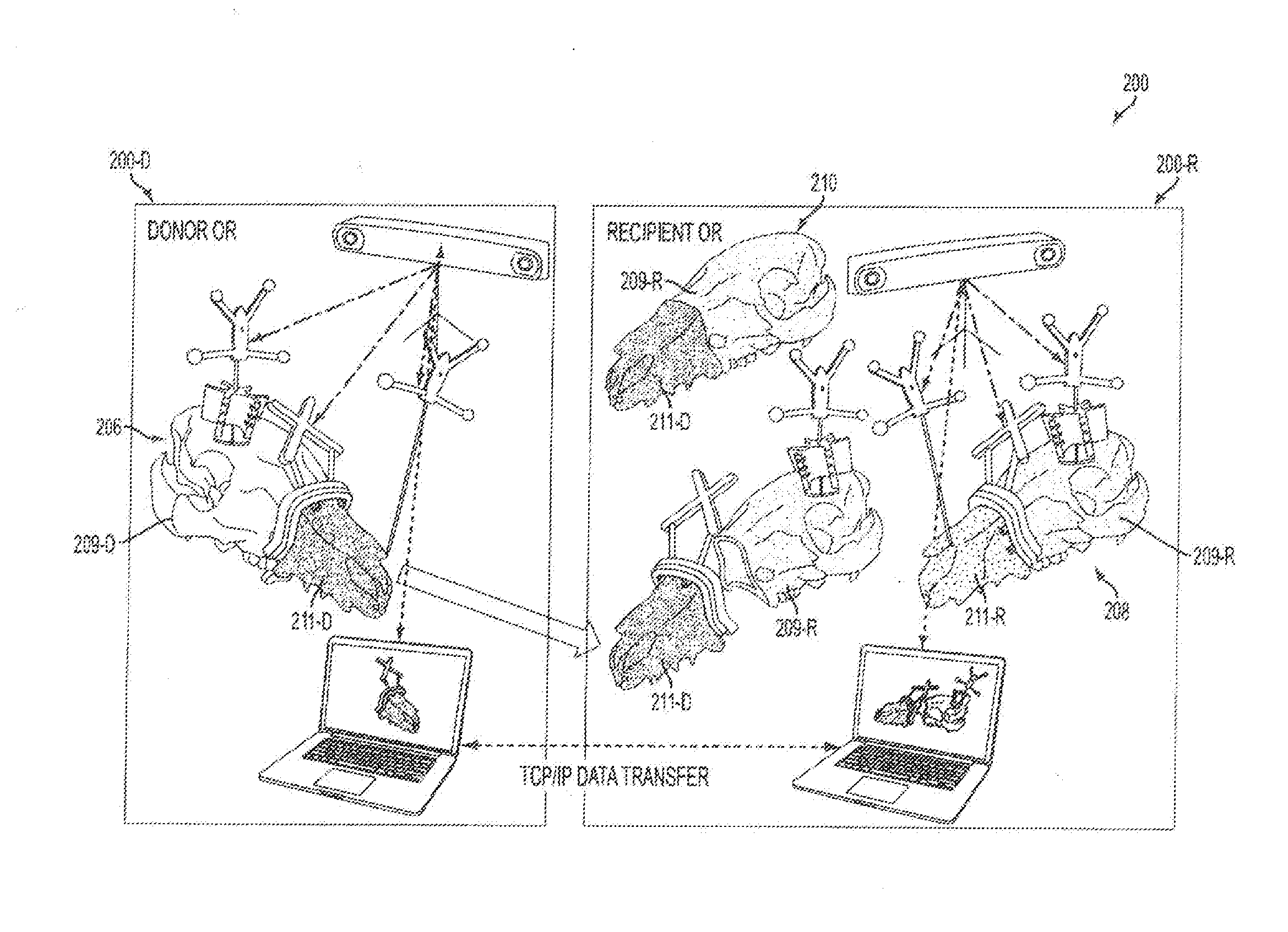
[0082]Live transplant surgeries (n=2) between four size-mismatched swine investigated whether or not an embodiment could actually assist a surgical team in planning and in executing a desired surgical plan. As shown in FIGS. 9A-9B, the first live surgery confirmed the proposed utility of overcoming soft and hard tissue discrepancies related to function and aesthetics. The final occlusal plane within the first recipient was ideal and consistent with the virtual plan as seen on lateral cephalogram as shown in FIG. 10C. Pre-operative functional predictions of donor-to-recipient occlusion were realized based on cephalometric analyses as shown in FIG. 9C performed both before and after surgery. Soft tissue inconsistencies of the larger-to-smaller swine scenario were also reduced following the predicted movements of face, jaw and teeth as shown in FIG. 10D.

[0083]The second live surgery showed improved success as compared to its predecessor due to surgeon familiarity and technology modific...

example 2

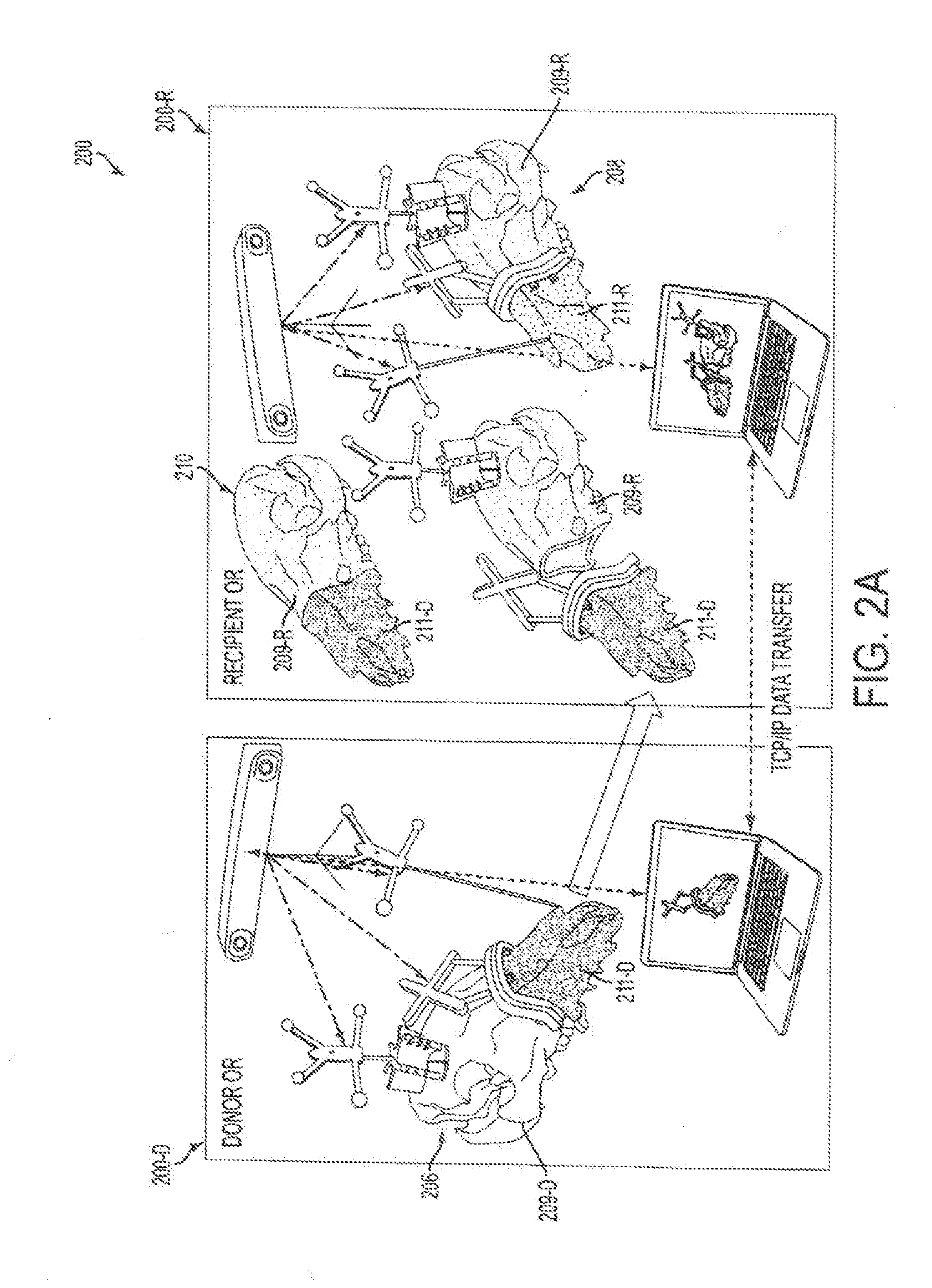
[0087]Female and male donor heads (n=2), double-jaw, Le Fort III-based alloflaps were harvested using handheld osteotomes, a reciprocating saw, and a fine vibrating reciprocating saw. Both osteocutaneous alloflaps were harvested using a double-jaw, Le Fort III-based design (a craniomaxillofacial disjunction), with preservation of the pterygoid plates, incorporating all of the midfacial skeleton, complete anterior mandible with dentition, and overlying soft tissue components necessary for ideal reconstruction.

[0088]Prior to transplantation, both scenarios were completed virtually given the gender-specific challenges to allow custom guide fabrication as shown in panels A-H of FIG. 12. Once assimilated, the donor orthognathic two-jaw units were placed into external maxilla-mandibular fixation (MMF) using screw-fixated cutting guides to retain occlusal relationships during the mock transplants as shown in panels A-D of FIG. 13.

[0089]As shown in FIGS. 13, 14A-14B, an embodiment of a cutt...


PUM


Abstract

A method for computer-assisted planning of a transplant surgery is provided. The method includes obtaining a computer-readable representation of a donor and recipient skeletal fragment; determining surgical cutting planes on the computer-readable representation of the donor skeletal fragment from which a portion of the donor skeletal fragment from the computer-readable representation of the donor skeletal fragment will be harvested; determining virtual cutting guides; performing a virtual osteotomy to separate the portion of the donor skeletal fragment from the computer-readable representation of the donor skeletal fragment from a remainder portion of the donor skeletal fragment based on a position of the virtual cutting guides that are attached to the computer-readable representation of the donor skeletal fragment; positioning the donor skeletal fragment within a transplant region of the recipient skeletal fragment; and creating a hybrid computer-readable representation comprising the recipient skeletal fragment and the portion of the donor skeletal.

Description

CROSS-REFERENCE TO RELATED APPLICATIONS[0001]This application claims priority from U.S. Provisional Patent Application Ser. No. 61 / 910,204, filed Nov. 29, 2013; 61 / 940,196, filed Feb. 14, 2014; and 62 / 049,866, filed Sep. 12, 2014, which are hereby incorporated by reference in their entirety.GOVERNMENT SUPPORT STATEMENT[0002]This invention was made with government support under NCATS Grant No. UL1TR000424-06 awarded by the National Institutes of Health. The government has certain rights in the invention.FIELD OF THE INVENTION[0003]This invention relates generally to the field of surgery, particularly craniomaxillofacial surgery, and specifically to the field of computer-assisted craniomaxillofacial surgery and all related orthognathic, neurosurgical and head / face / neck surgical procedures and associated methods, tools and systems.BACKGROUND OF THE INVENTION[0004]Face-jaw-teeth transplantation represents one of the most complicated scenarios in craniomaxillofacial surgery due to the sk...

Claims


Application Information

Patent Timeline
IPC IPC(8): A61B34/10G06F19/00A61B34/20G16H20/40G16H30/40G16H50/50
CPCA61B34/10A61B34/20G06F19/3481A61B2034/2065A61B2034/108A61B2034/2055A61B2034/105A61B17/176G16H50/50A61B17/1739Y02A90/10G16H30/40G16H20/40A61B2034/2051A61B17/15A61B17/1695A61B17/8085A61F2/2803
Inventor GORDON, CHADARMAND, MEHRANMURPHY, RYANGRANT, GERALDLIACOURAS, PETERWOLFE, KEVINBASAFA, EHSAN
Owner THE JOHN HOPKINS UNIV SCHOOL OF MEDICINE
Learn More