Machine tool capable of reducing thermal error

a technology of machine tools and thermal errors, applied in the field of machine tools, can solve the problems of reducing the difference in temperature, reducing processing precision, and likely and reducing thermal errors, so as to minimize the thermal deformation of the main shaft and reduce thermal errors. , the effect of reducing the thermal error

Inactive Publication Date: 2017-01-05
NATIONAL CHUNG HSING UNIVERSITY
View PDF13 Cites 5 Cited by
  • Summary
  • Abstract
  • Description
  • Claims
  • Application Information

AI Technical Summary

Benefits of technology

[0006]It is an objective of the present invention to provide a machine tool capable of reducing thermal errors and thus minimizing the thermal deformation of a main shaft without augmenting structural complexity, so as to enhance processing precision and cut manufacturing cost.

Problems solved by technology

Unless an appropriate heat dissipation mechanism is available, the main shaft will be likely to deform because of uneven distribution of ambient temperature.
The deformation of the main shaft renders the processing precision difficult to correct.
Nonetheless, the circulation of the cooling fluid is accompanied by a gradual increase in the temperature of the cooling fluid, thereby dwindling the difference in temperature between the cooling fluid and the main shaft and thus deteriorating the cooling efficiency.
Unfortunately, the cooling chip is disadvantageously ineffective in minimizing the thermal deformation of the main shaft.
Unfortunately, the table must come with the cooling chip and a cooling channel and requires a related apparatus which pressurizes the cooling fluid, and in consequence China patent CN202106241 and China patent CN202129679 have drawbacks follows: exacerbation of structural complexity, high manufacturing cost, and failure of the cooling chip and the cooling fluid to optimize the heat dissipation of the main shaft.

Method used


Image

  • Machine tool capable of reducing thermal error
  • Machine tool capable of reducing thermal error
  • Machine tool capable of reducing thermal error

Examples


Embodiment Construction

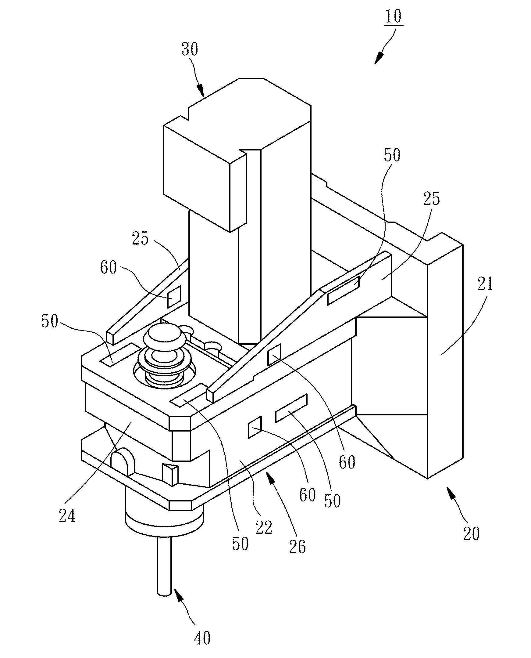
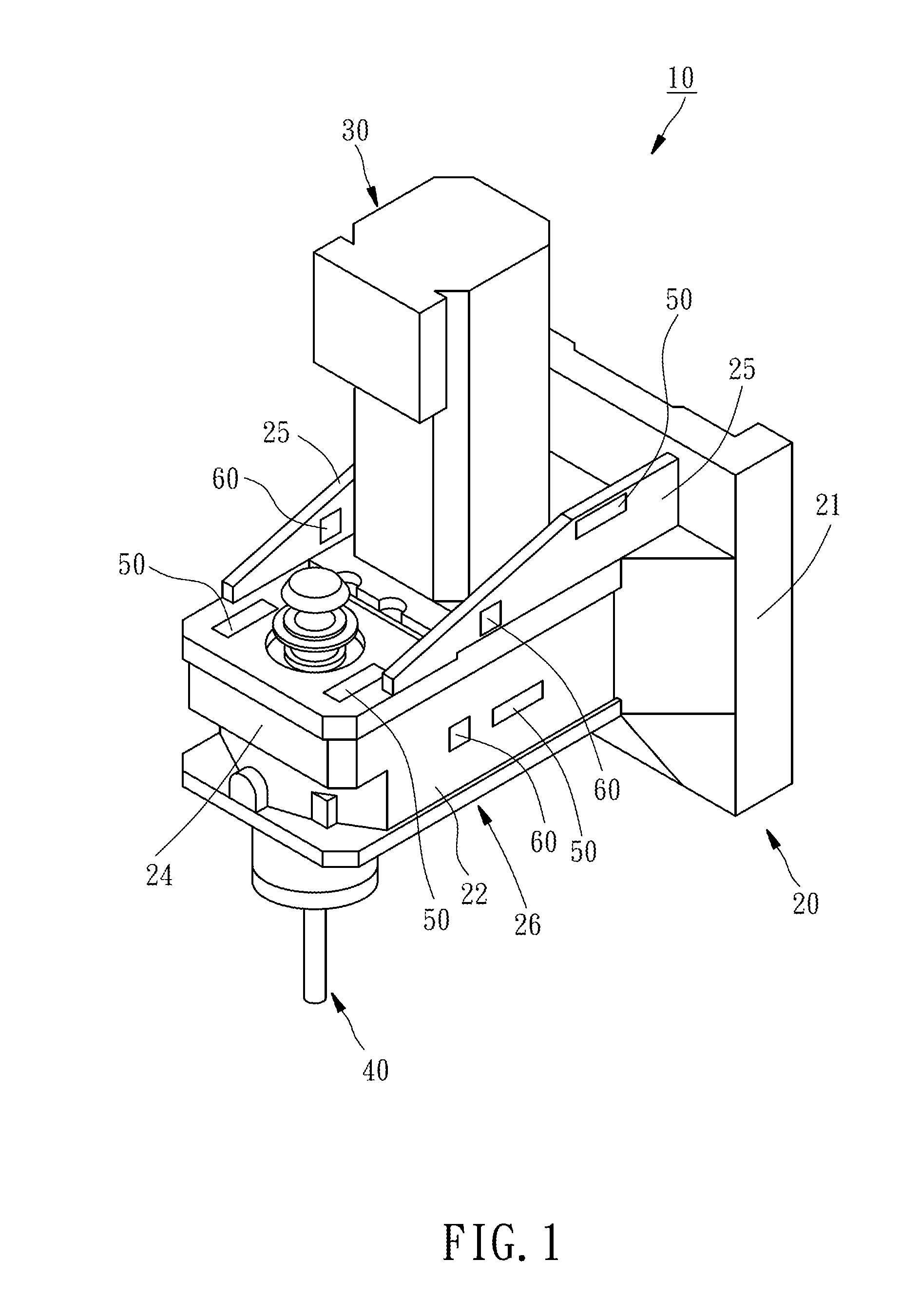
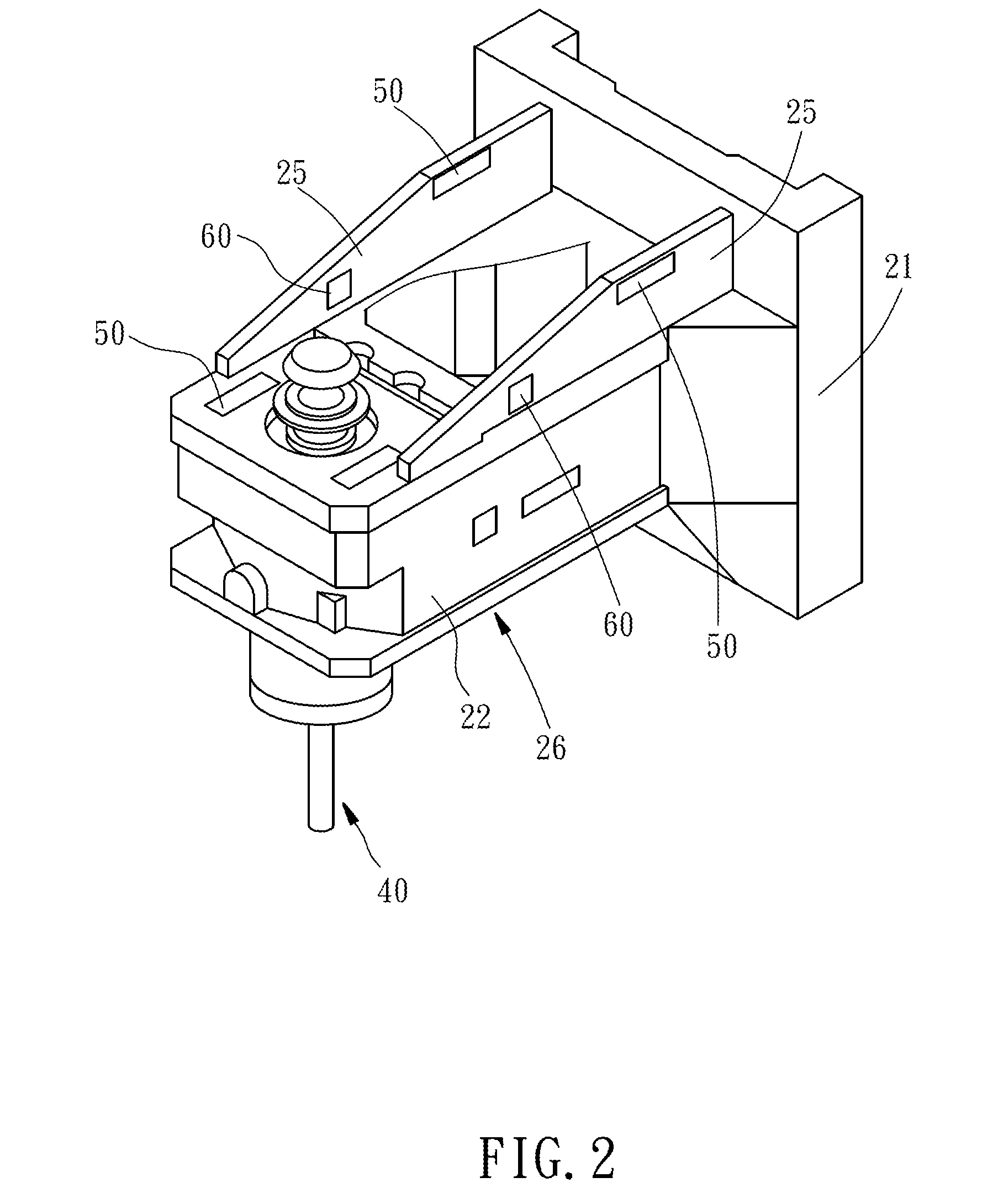
[0018]Referring to FIG. 1 through FIG. 4, a machine tool 10 of the present invention comprises a table 20, a driving source 30, a main shaft 40, and a plurality of electric heating pieces 50.

[0019]The table 20 comprises an upright post 21 and a main shaft support element 26. The main shaft support element 26 comprises a cantilever beam 22 and two opposing ribbed plates 25. The cantilever beam 22 comprises a fixed end 23 and a free end 24. The cantilever beam 22 is fixed to the front of the upright post 21 through the fixed end 23. The ribbed plates 25 are connected between the front of the upright post 21 and the top surface of the cantilever beam 22.

[0020]The driving source 30 is mounted on the cantilever beam 22 of the table 20 to exert a driving force.

[0021]The main shaft 40 is disposed at a free end 24 of the cantilever beam 22 of the table 20 and connected to the driving source 30 through a transmission belt (not shown); hence, the main shaft 40 is driven by the driving source ...


PUM


Abstract

A machine tool includes a table, a main shaft, and an electric heating piece. The table includes an upright post and a main shaft support element connected to the upright post. The main shaft is rotatably disposed at the main shaft support element of the table. The electric heating piece is disposed at the main shaft support element of the table and positioned on a side of the main shaft, wherein the side of the main shaft manifests a lower thermal deformation level. The regulation of the electric heating piece minimizes the nonlinear thermal deformation of the main shaft, thereby enhancing processing precision.

Description

BACKGROUND OF THE INVENTION[0001]1. Technical Field[0002]The present invention relates to machine tools and, more particularly, to a machine tool capable of reducing thermal errors.[0003]2. Description of Related Art[0004]A motor drives a main shaft of a machine tool to rotate at a high speed while the machine tool is operating. Much heat is generated from the machine tool, as the main shaft undergoes high-speed rotation. Unless an appropriate heat dissipation mechanism is available, the main shaft will be likely to deform because of uneven distribution of ambient temperature. The deformation of the main shaft renders the processing precision difficult to correct.[0005]The related prior art involves providing a channel to a table such that a main shaft undergoes heat dissipation with a cooling fluid inside the channel. Nonetheless, the circulation of the cooling fluid is accompanied by a gradual increase in the temperature of the cooling fluid, thereby dwindling the difference in te...

Claims


Application Information

Patent Timeline
Patent Type & Authority Applications(United States)
IPC IPC(8): B23Q11/00B23Q11/12B23Q11/14
CPCB23Q11/0003B23Q11/128B23Q11/143
Inventor LEE, MING-TSANGCHEN, JENQ-SHYONGHO, CHIH-CHERNGHUNG, MING-CHIEH
Owner NATIONAL CHUNG HSING UNIVERSITY
Why Eureka
Try Eureka