
Hybrid drive device

a hybrid drive and drive technology, applied in the direction of vehicle sub-unit features, transportation and packaging, gearing, etc., can solve the problem that the torque on the rotating member can easily be cancelled, and achieve the effect of reducing the torque of the engine, avoiding deterioration of components, and avoiding the generation of wear

Active Publication Date: 2017-01-05
TOYOTA JIDOSHA KK
View PDF0 Cites 6 Cited by
  • Summary
  • Abstract
  • Description
  • Claims
  • Application Information

AI Technical Summary

Benefits of technology

The hybrid drive device described in this patent prevents damage to components and avoids wear and noise during combustion anomalies or device anomalies. This is achieved by keeping the selectable one-way clutch in a free mode, even if certain conditions for engagement are not met. In the locked mode, the motor-generator is controlled to stop its functions as an electric motor and as a generator, allowing the selectable one-way clutch to free-wheel. This prevents the engine torque from being supported and reduces the torque on the rotating member, minimizing adverse effects on the selectable one-way clutch.

Problems solved by technology

Since, when the motor-generator is controlled to be in a shut-down state, the reaction torque of the engine torque cannot be supported by the motor torque of the motor-generator, accordingly, if an anomaly in the combustion of the engine occurs and the engine torque drops, the torque upon the rotating member can easily become cancelled.

Method used


Image

  • Hybrid drive device
  • Hybrid drive device
  • Hybrid drive device

Examples


embodiment # 1

Embodiment #1

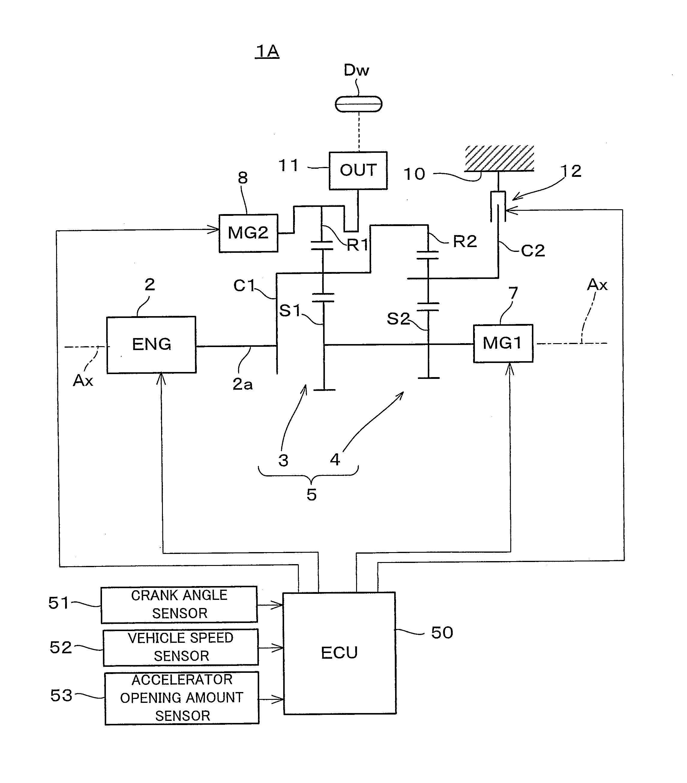
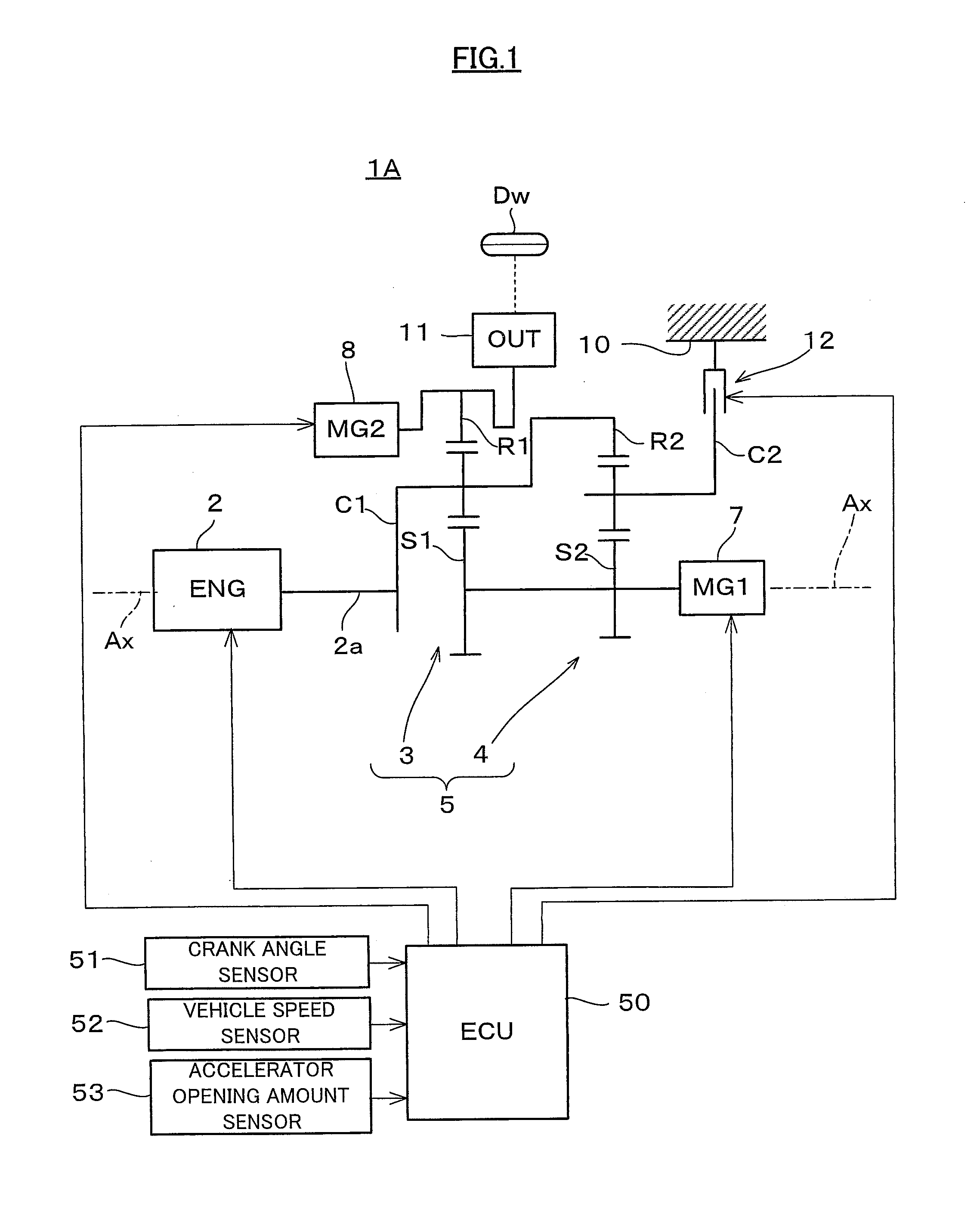
[0025]As shown in FIG. 1, a vehicle 1A is built as a hybrid vehicle to which a hybrid drive device according to a first embodiment of the present invention is applied. This vehicle 1A comprises a spark ignition type internal combustion engine 2 which serves as an engine, a power split mechanism 5 which serves as a differential mechanism, and two motor-generators 7 and 8. The power split mechanism 5, the motor-generators 7 and 8, and power transmission elements of various kinds are received within a casing 10.

[0026]The power split mechanism 5 is built as a combination of two planetary gear mechanisms 3 and 4 which are of the single pinion type. A sun gear S1 of the first planetary gear mechanism 3 and a sun gear S2 of the second planetary gear mechanism 4 are joined together so as to rotate as a unit, and a carrier C1 of the first planetary gear mechanism 3 and a ring gear R2 of the second planetary gear mechanism 4 are joined together so as to rotate as a unit. Due to t...

embodiment # 2

Embodiment #2

[0049]Next, a second embodiment of the present invention will be explained with reference to FIGS. 9 and 10. The structure of a hybrid vehicle 1B to which a hybrid drive device according to this second embodiment has been applied is schematically shown in FIG. 9. This vehicle 1B differs from the vehicle 1A of the first embodiment in that it has a different structure for the power split mechanism 60, a different structure from the power split mechanism 60 to the drive wheels Dw, and a different location for mounting of the clutch 12. Since the other structural elements of this vehicle 1B are the same as corresponding ones of the vehicle 1A, accordingly the structures which are common to this vehicle 1B and the vehicle 1A will be denoted in FIG. 9 by the same reference symbols, and explanation thereof will be curtailed.

[0050]The power split mechanism 60 is built as a single pinion type planetary gear mechanism, and comprises a sun gear S which is an externally toothed gea...


PUM


Abstract

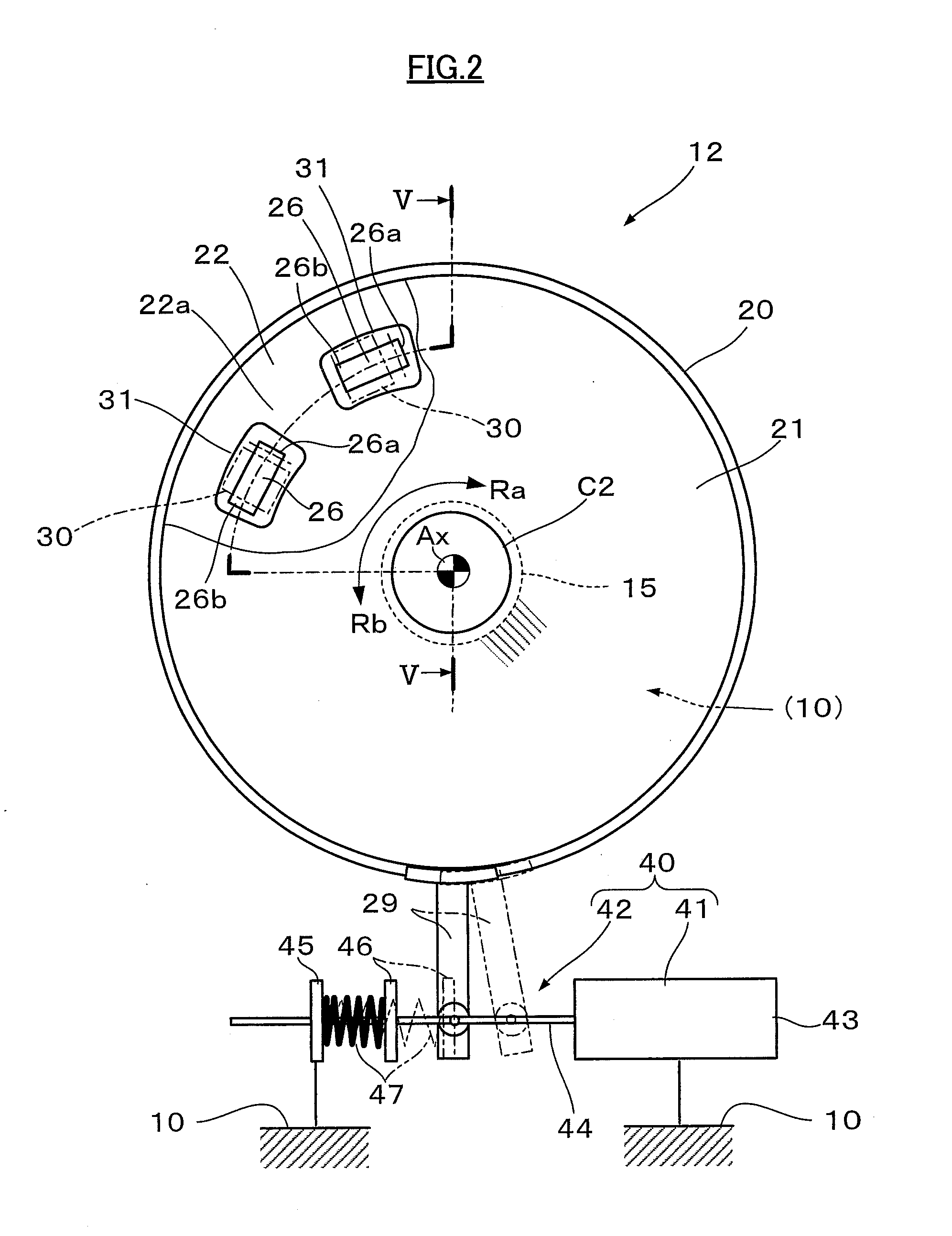
The hybrid drive device of the present invention includes a selectable one-way clutch 12 that includes a rotational plate that is capable of receiving the reaction torque of an internal combustion engine and that is provided to a power split mechanism, and that can be changed over between: a locked mode in which, in the state of receiving the reaction torque, positive rotation of the rotational plate is prevented while negative rotation of the rotational plate in the direction opposite to the positive rotation is permitted; and a free mode in which, in the state of receiving the reaction torque, the positive rotation and the negative rotation of the rotational plate are both permitted. And, when misfiring of the internal combustion engine occurs, the selectable one-way clutch is kept in the free mode.

Description

INCORPORATION BY REFERENCE[0001]The disclosure of Japanese Patent Application NO. 2015-132769 filed on Jul. 1, 2015, including the specification, drawings and abstract is incorporated herein by reference in its entirety.BACKGROUND OF THE INVENTION[0002]Field of the Invention[0003]The present invention relates to a hybrid drive device to which an engine and a motor-generator are provided as sources of drive power.[0004]Description of the Related Art[0005]In a hybrid drive device, a system is per se known in which a dog clutch DC3 and a one-way clutch OC3 are provided between a rotor shaft of a first motor-generator MG1 and a case C of a hybrid transaxle, and in which one engagement member of the dog clutch DC3 is connected to the one-way clutch OC3 while the other engagement member of the dog clutch DC3 is fixed to the case C (see Japanese Patent Application Publication No. 2010-36880 (JP-A-2010-36880)). With this type of hybrid drive device, by controlling the dog clutch DC3 to be i...

Claims


Application Information

Patent Timeline
IPC IPC(8): B60K6/383F16H48/20F16H48/10B60K6/365B60K6/442B60L50/16
CPCB60K6/383F16H2048/202B60K6/442F16H48/10F16H48/20Y10S903/913Y10S903/91Y10S903/946B60Y2200/92B60Y2300/424B60Y2300/182B60Y2400/80B60Y2400/427F16D41/125F16D41/04F16D48/06B60K6/365B60K6/387B60K6/445F16D41/02F16D41/14Y02T10/62F16D41/16F16D41/26
Inventor ITAGAKI, KENJIMAGARIDA, NAOFUMI
Owner TOYOTA JIDOSHA KK
Learn More