Regenerator for a thermal cycle engine

Inactive Publication Date: 2017-01-05
NV BEKAERT SA
View PDF10 Cites 0 Cited by
  • Summary
  • Abstract
  • Description
  • Claims
  • Application Information

AI Technical Summary

Benefits of technology

[0010]The primary objective of the invention is to provide a r

Problems solved by technology

However, experiments have shown that in this way it is not possible to keep th

Method used


Image

  • Regenerator for a thermal cycle engine
  • Regenerator for a thermal cycle engine

Examples


Embodiment Construction

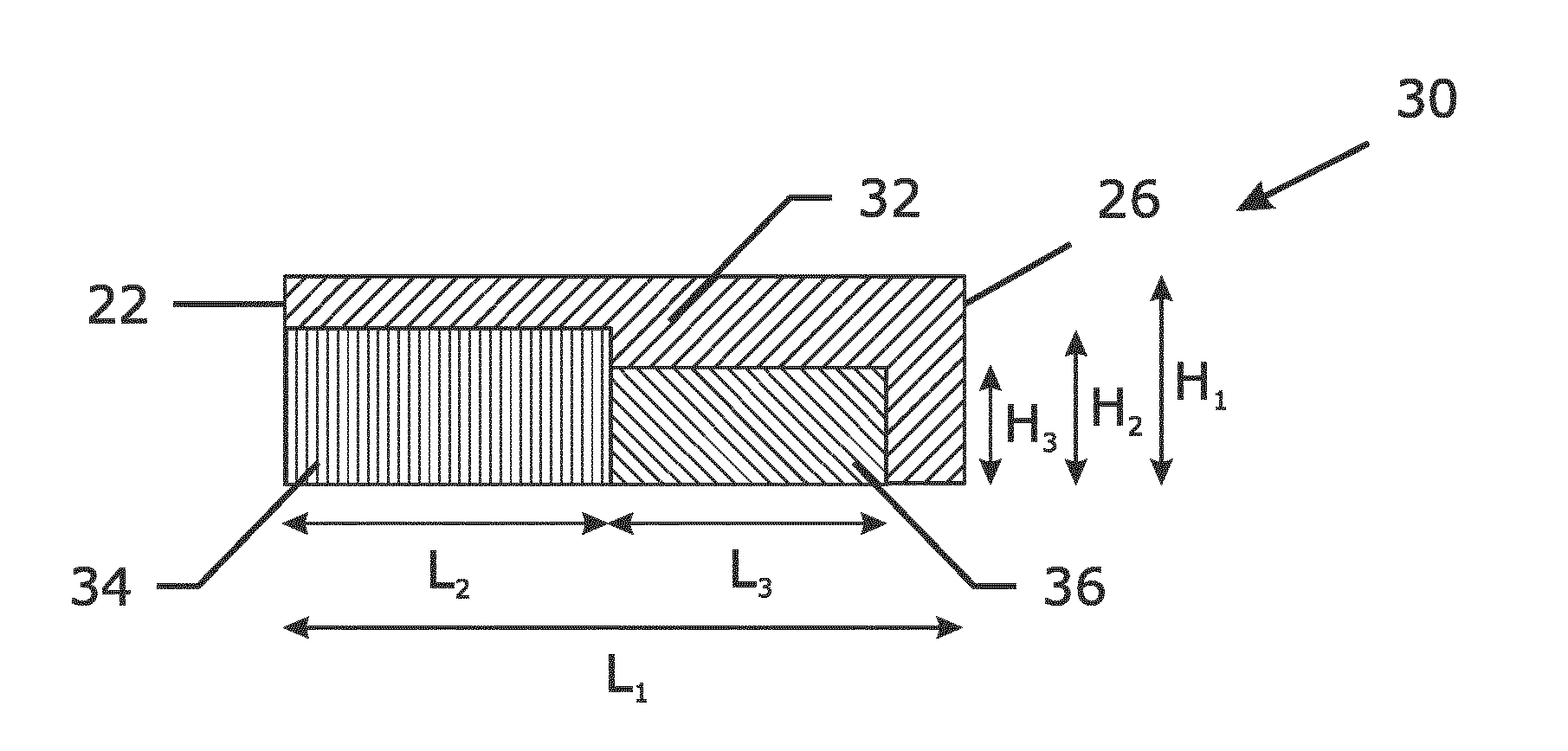
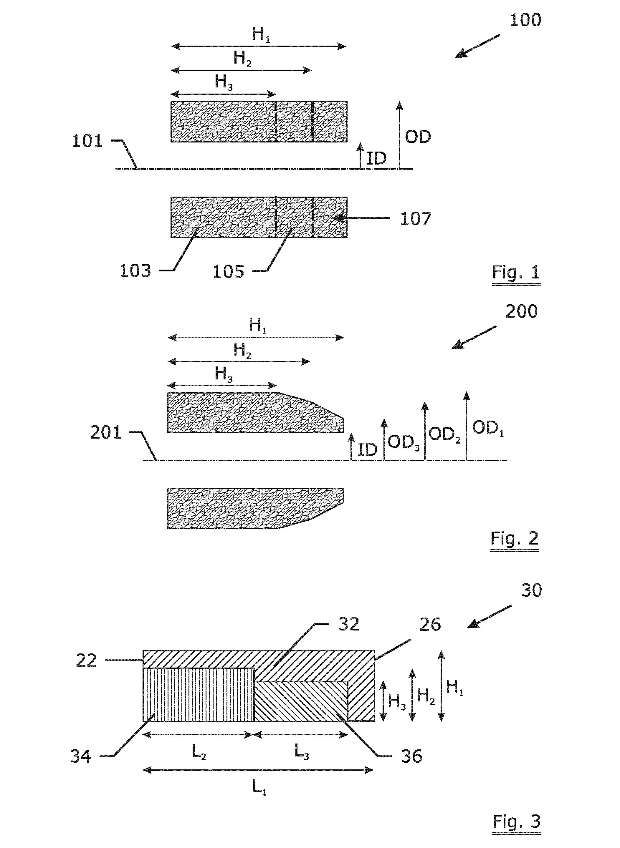
[0045]FIG. 1 shows an example 100 of a regenerator ring according to the invention. The regenerator has a central axis of symmetry 101. The regenerator has over its axial length H1 a constant cross sectional shape and size. The regenerator ring has an axial length H1, e.g. 72 mm. The inner diameter is ID, e.g. 143 mm and the outer diameter is OD, e.g. 221 mm. The regenerator ring has three sections with different porosity levels, a first section 103 with a length H3, e.g. of 48 mm of a first porosity of e.g. 90%, a second section 105 with a length H2-H3 (e.g. 60 mm-48 mm=12 mm) of a higher porosity than the first porosity, e.g. 92.4%; and a third section 107 with a length H1-H2 (e.g. 72 mm-60 mm=12 mm) of a still higher porosity, e.g. 94.6%.

[0046]FIG. 2 shows another example 200 of a regenerator ring according to the invention. The regenerator has a central axis of symmetry 201. The regenerator has over its axial length H1, e.g. 72 mm, different cross sectional shapes and sizes. The...


PUM

PropertyMeasurementUnit
Lengthaaaaaaaaaa
Lengthaaaaaaaaaa
Sizeaaaaaaaaaa

Abstract

The regenerator has a central axis. The regenerator has a multitude of web layers wound around the central axis. The web layers are formed by two or more metal fiber or metal wire having webs wound around the central axis. When observed from the central axis to the outside of the regenerator, at least one web layer of a web of a first width is followed by a web layer of a web of a width larger than the web of a first width.

Description

TECHNICAL FIELD[0001]The invention relates to a regenerator for a thermal cycle engine, e.g. a stirling engine, and to a method for manufacturing such a regenerator.BACKGROUND ART[0002]A regenerator is used in a thermal cycle engine to add or remove heat from the working fluid during the different phases of the thermal cycle. Regenerators are important parts for defining the efficiency of thermal cycle engines (e.g. stirling engines).[0003]A regenerator needs to have a very low thermal conductivity in the fluid flow direction—which is along the axis of the regenerator—, since one end of the regenerator is hot and the other end is cold. The regenerator needs to have very high thermal conductivity in the direction normal to the fluid flow so that the working fluid can rapidly adjust itself to the local temperature inside the regenerator. The regenerator must have a very large specific surface area to improve the rate of heat transfer of the working fluid. The regenerator must have a l...

Claims


Application Information

Patent Timeline
IPC IPC(8): F02G1/057B23P15/26F28D17/02
CPCF02G1/057B23P15/26F02G2257/00F28D17/02Y10T29/49357
Inventor VERSCHAEVE, FRANK
Owner NV BEKAERT SA
Why Eureka
Try Eureka