Touch detection device used in water handling equipment, and faucet apparatus including the same

a technology of touch detection and water handling equipment, which is applied in the direction of instruments, lighting and heating equipment, pulse techniques, etc., can solve the problems of false sensing, inability to operate, and relative large operating force required to operate the switch, so as to prevent false sensing

Active Publication Date: 2017-01-05
TOTO LTD
View PDF26 Cites 12 Cited by
  • Summary
  • Abstract
  • Description
  • Claims
  • Application Information

AI Technical Summary

Benefits of technology

[0059]Using the touch detection device of the present invention and a faucet apparatus comprising same, operation can be performed with a light touch, and false operation can be prevented even when used in water handling equipment.

Problems solved by technology

However, in the piezo-electric switch set forth in Japanese Published Unexamined Patent Application 54-153284 (Patent Document 1), pressure is applied to the piezo-electric element causing it to elastically deform, and the switch operation is sensed using the electrical charge produced by this elastic deformation, creating the problem that a relatively large operating force is required to operate the switch, and operation is not possible with a light touch.
However because the vibrating state of the vibrating circuit is extremely sensitive to circuit constants, when the piezo-electric for sensing operation is placed in a location separated from the vibration circuit, the problem arises that the vibration state can become unstable, causing false sensing.
As a result, the inductance and stray capacitance of this lead line may destabilize the vibrating circuit operation, causing false operations.
In this case, because the operating portion is disposed close to the spout opening of the faucet apparatus, the entire vibrating circuit must be built-in close to the spout opening, and freedom of design for the faucet apparatus is greatly restricted.

Method used


Image

  • Touch detection device used in water handling equipment, and faucet apparatus including the same
  • Touch detection device used in water handling equipment, and faucet apparatus including the same
  • Touch detection device used in water handling equipment, and faucet apparatus including the same

Examples


first embodiment

[0149]Next, referring to FIGS. 4 and 5, we explain the principle of detection in a touch detection device according to the invention.

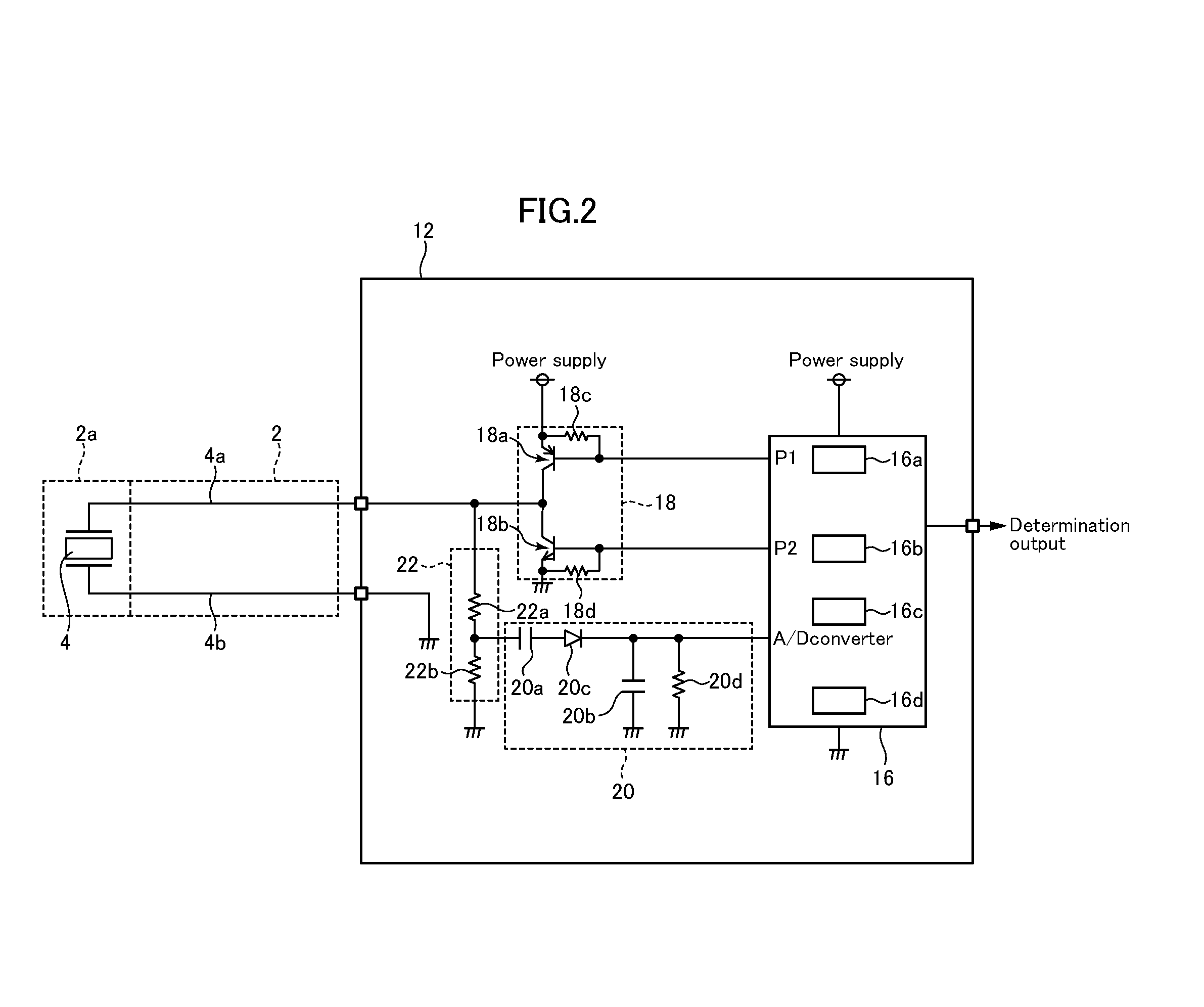
[0150]In a touch detection device according to a first embodiment of the invention, FIG. 4 shows a typical output waveform from the piezo-electric element 4 when a user does not touch the sensing portion 2a, and FIG. 5 shows a typical output waveform from the piezo-electric element 4 when a user touches the sensing portion 2a. Note that FIGS. 4 and 5 show the output voltage waveform from the output ports P1, P2 (FIG. 2) of the microcomputer 16 on the top, the output voltage waveform of the piezo-electric element 4 (the voltage waveform between the signal lines 4a and 4b) in the middle, and the output voltage waveform from the signal conversion circuit 20 (input waveform to the microcomputer 16 A / D converter) on the bottom. Also, FIGS. 4 and 5, etc, show signal waveforms schematically, and differ from actual waveforms with respect to items such as the n...

second embodiment

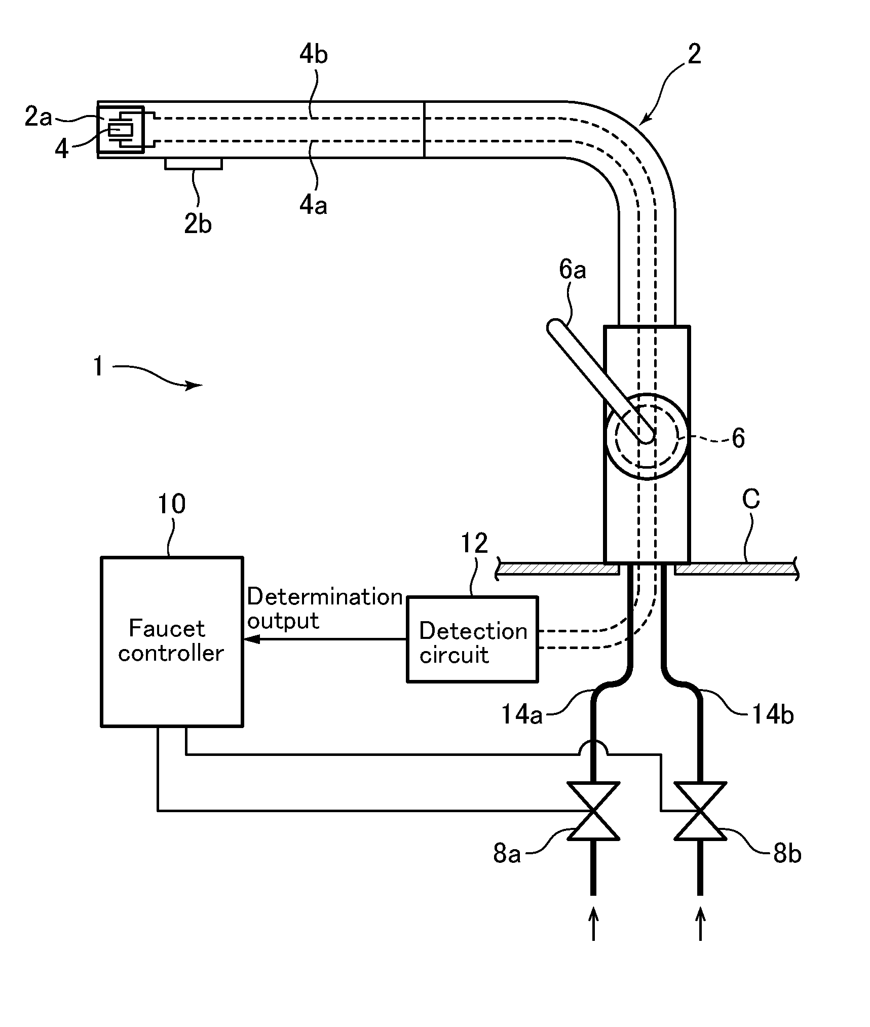
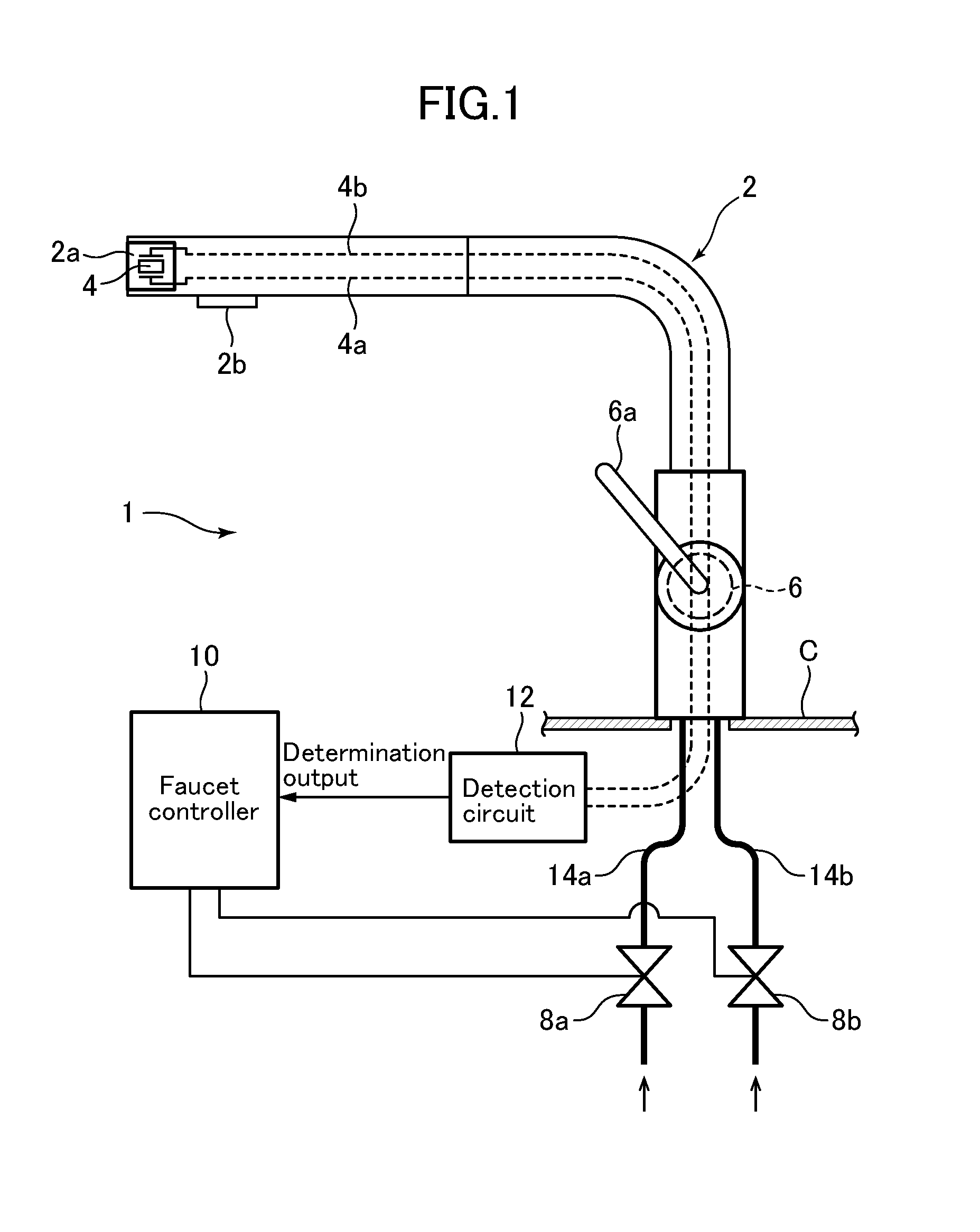
[0222]Next, referring to FIGS. 16 through 21, we explain the operation of a faucet apparatus 1 according to the invention.

[0223]In the faucet apparatus of the present embodiment, only the “touch detection” processing and the “touch confirming detection” processing called as respective subroutines from the main flow steps S3 and S6 in FIG. 6 differ from the first embodiment described above. Therefore here we explain only the aspects of the second embodiment of the invention different from the first embodiment of the invention, and we omit an explanation of similar parts.

[0224]FIG. 16 is a touch detection flow called as a subroutine from the main flow in FIG. 6 in a second embodiment of the invention. FIG. 17 is a diagram showing a typical output waveform at a piezo-electric element when a user is not touching the sensing portion in a second embodiment touch detection device of the invention. FIG. 18 is a diagram showing a typical output waveform at a piezoelectric element when a user...

third embodiment

[0237]Next, referring to FIGS. 22 through 32, we explain a faucet apparatus 1 according to the invention.

[0238]The faucet apparatus of the present embodiment differs from the first embodiment only with respect to the detection circuit constitution and effect. Therefore here we explain only the aspects of the third embodiment of the invention different from the first embodiment of the invention, and we omit an explanation of similar parts.

[0239]In the above-described invention, the first and second embodiments are touch detection devices used in a water handling apparatus; an AC voltage at a frequency matching the sensing portion 2a resonant frequency is intermittently applied, and sensing of contact by user's hand, etc. with the sensing portion 2a was based on sensing portion 2a reverberation vibration (FIG. 4) after stopping the application of AC voltage. I.e., determination of a “touch” to the sensing portion 2a is made based on the characteristic that when a user's hand contacts ...


PUM

PropertyMeasurementUnit
resonant frequencyaaaaaaaaaa

Abstract

A touch detection device capable of operation by a light touch, and of preventing false operations even when used in water handling equipment includes a sensing portion for sensing contact by a target object; a vibration excitation element attached to this sensing portion, a drive circuit for exciting vibration in the sensing portion, and a contact determining circuit for determining whether a target object is contacting a sensing portion based on vibration of the sensing portion after stopping the application of an AC voltage to the vibration excitation element by this drive circuit.

Description

TECHNICAL FIELD[0001]The present invention pertains to a touch detection device, and more particularly to a touch detection device used for water handling equipment, and a faucet apparatus comprising same.BACKGROUND ART[0002]Water handling equipment capable of sensing user operations using a switch or sensor and switching between spouting or shutting off water, or changing the form of water spouting, based on the sensed operation, are starting to be widely adopted. Such faucets or other water handling equipment used for water handling in kitchens, sinks, toilets, bathrooms, and the like are used in environments where water leakage can easily occur, where usage frequency is extremely high, and long durability is expected. Switches or sensors used to sense operations therefore preferably do not include mechanical electrical contacts.[0003]Optoelectric sensors used in automatic faucets and the like have the advantage of touch-free operation, but have slow response and are difficult to ...

Claims


Application Information

Patent Timeline
Patent Type & Authority Applications(United States)
IPC IPC(8): G01N29/12G01H11/08
CPCF16K31/02F16K37/0091H03K17/96H03K17/964H03K2217/96003Y10T137/0318Y10T137/9464E03C1/055F21V33/004E03C1/05G01L1/14G06F3/0436G01H11/08G01N29/12
Inventor KANEKO, YOSHIYUKI
Owner TOTO LTD
Why Eureka
Try Eureka