Slice image creation device and three-dimensional printing system

a three-dimensional printing and image creation technology, applied in image enhancement, programme control, instruments, etc., to achieve the effect of reducing the computation load, and reducing the amount of data

Inactive Publication Date: 2017-01-05
ROLAND DG CORP
View PDF0 Cites 7 Cited by
  • Summary
  • Abstract
  • Description
  • Claims
  • Application Information

AI Technical Summary

Benefits of technology

[0020]In the above-described preferred embodiment, in the first divided slice image, the second divided slice image and the target slice image, the printing region (divided printing region, and target printing region) and the non-printing region (divided non-printing region, and target non-printing region) are represented with different colors from each other. Therefore, the computation of obtaining the target slice image from the first divided slice image and the second divided slice image is a simple computation of merely comparing pixel values of the pixels. This facilitates the computation performed on the printing regions and the computation performed on the non-printing regions in the first divided slice image and the second divided slice image, which are pre-division slice images. In addition, unlike with the conventional complicated computation method of obtaining a target slice image by peeling performed on a slice model defined by a plurality of contours, a computation failure caused by peeling, which is easily caused in a multiplexed portion where a plurality of contours cross each other is avoided. Therefore, a better computation result is provided, and the amount of computation is decreased. The data capacity is also decreased. This shortens the processing time.
[0022]In the above-described preferred embodiment, the pre-process processor performs the smoothing process on the target object model to decrease the amount of data of the target object model. This allows the topology construction processor, the division determination processor, the division processor, the slice model creation processor, the slice image creation processor and the synthesis processor to use the target object model having the amount of data decreased by the pre-process processor. This preferably decreases the computation load.

Problems solved by technology

Therefore, conventionally, a target slice image corresponding to the target object model is not created, and thus a desired target slice image is not created.
This solves the problem with the conventional art that a contour of a desired target slice model is not extracted because peeling is not performed properly on the target object model.

Method used


Image

  • Slice image creation device and three-dimensional printing system
  • Slice image creation device and three-dimensional printing system
  • Slice image creation device and three-dimensional printing system

Examples


embodiment 1

Preferred Embodiment 1

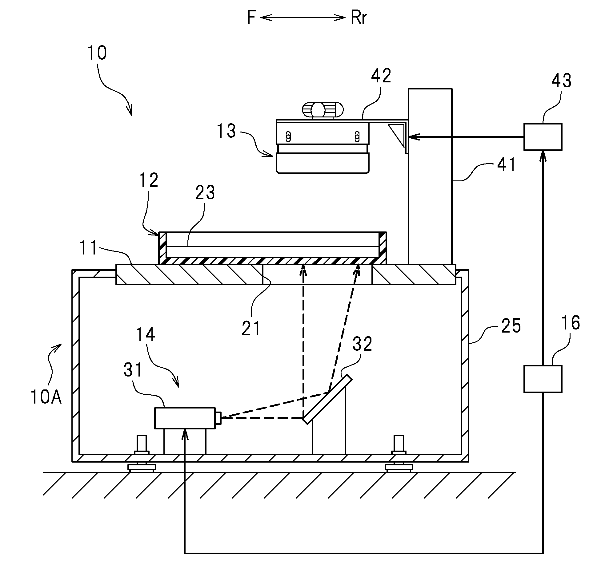
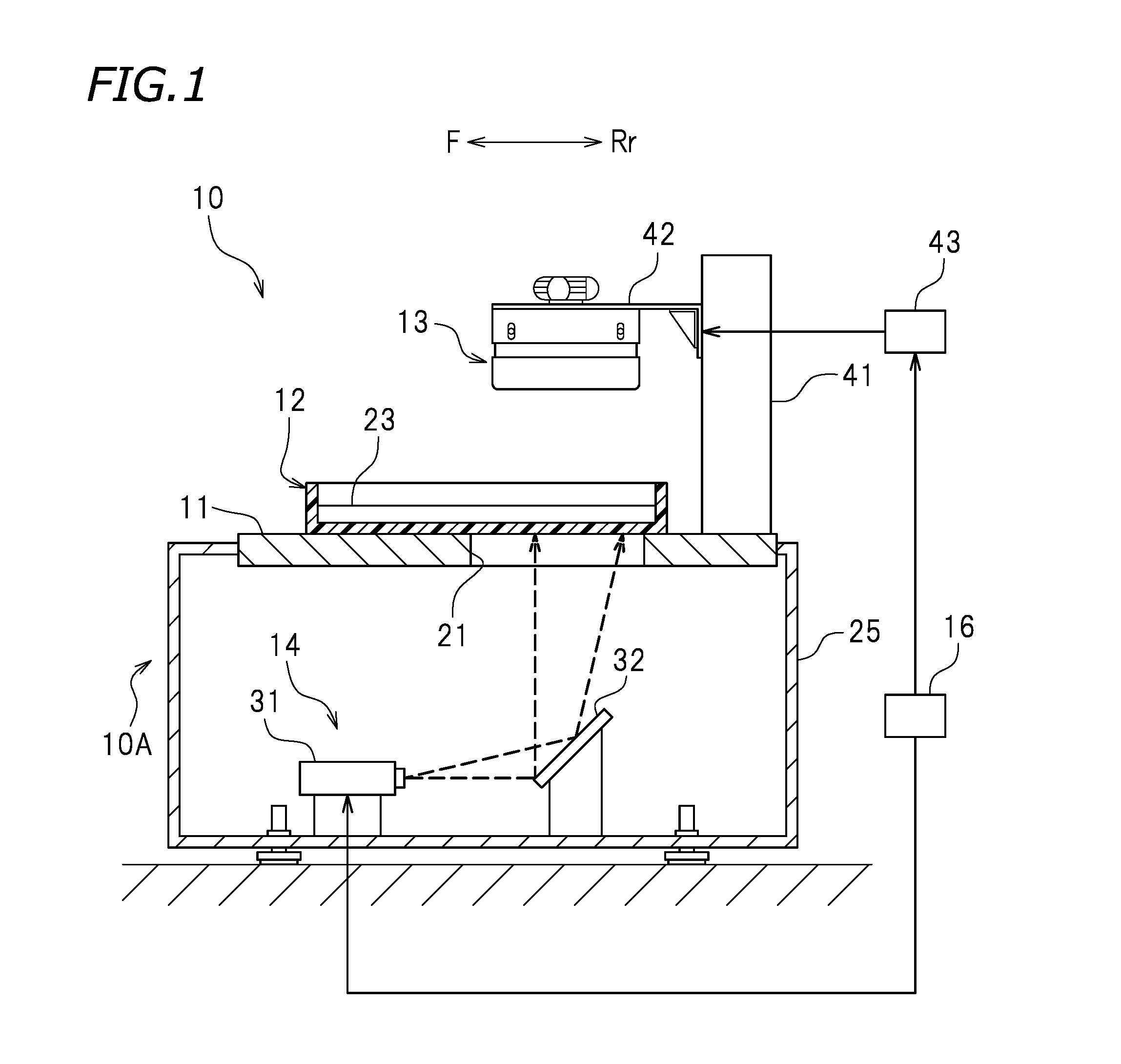
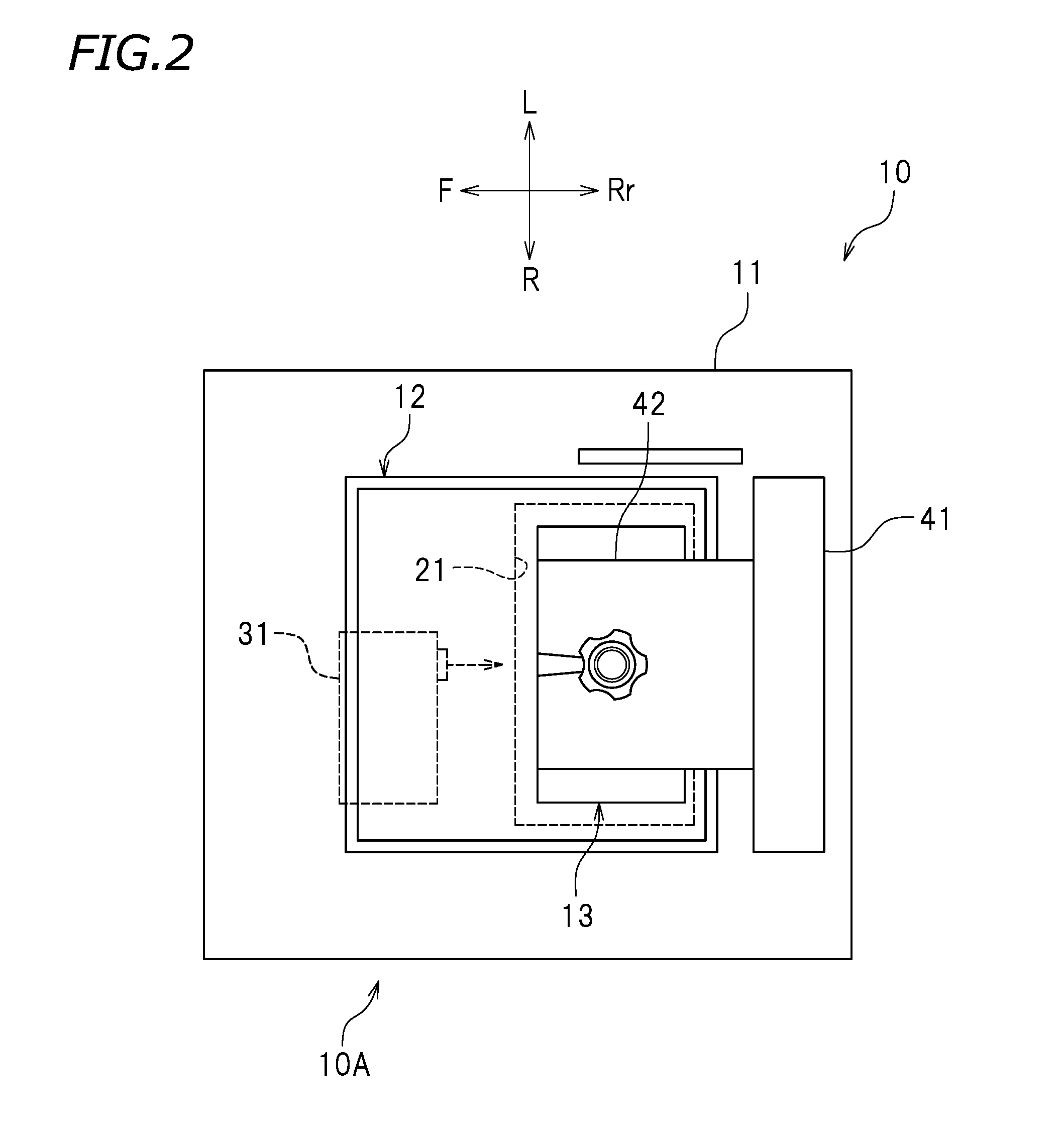
[0050]FIG. 1 is a cross-sectional view of a three-dimensional printing system 10 in this preferred embodiment. FIG. 2 is a plan view of the three-dimensional printing system 10. In the drawings, letters F, Rr, L and R respectively represent front, rear, left and right. These directions are provided merely for the sake of convenience, and do not limit the form of installation of the three-dimensional printing system 10 in any way.

[0051]The three-dimensional printing system 10 is a system that prints a three-dimensional object. As shown in FIG. 1, the three-dimensional printing system 10 includes a three-dimensional printing device 10A and a slice image creation device 100 (see FIG. 5). A cross-sectional shape of a three-dimensional object is prepared in advance. The three-dimensional printing device 10A cures a photocurable resin in a liquid state to form a resin layer having a shape corresponding to a prepared cross-sectional shape of a three-dimensional object...

embodiment 2

Preferred Embodiment 2

[0095]FIG. 18 is a perspective view of a target object model 110. FIG. 19 shows a topology list 120 of the target object model 110 shown in FIG. 18. Even the target object model 110 shown in FIG. 18 may be divided into a plurality of divided object models to create target slice images. In this example, a procedure of dividing the target object model 110 will be described.

[0096]First, like in step S103 shown in FIG. 6, the division determination processor 58 calculates the number of topology groups from the topology list 120 shown in FIG. 19. The topology list 120 shown in FIG. 19 includes topology groups T41 and T42. Therefore, the number of the topology groups is “2”, namely, there are a plurality of topology groups. The division determination processor 58 determines whether or not there is an apex, among the apexes defining the target object model 110, at which the target object model 110 is divided in correspondence with the topology groups. In this example,...


PUM

PropertyMeasurementUnit
thicknessaaaaaaaaaa
colorsaaaaaaaaaa
photocurableaaaaaaaaaa

Abstract

In a slice image creation device, a topology construction processor constructs a topology to create a topology list of a target object model. A division determination processor determines whether or not there is a ridgeline or an apex at which the target object model is divisible in correspondence with topology groups. A division processor, in a case that, for example, there is a ridgeline that is in contact with 4 planes, divides the target object model into at least a first divided object model and a second divided object model along the ridgeline that is in contact with 4 planes. A slice image creation processor creates a first divided slice image and a second divided slice image respectively corresponding to the first divided object model and the second divided object model. A synthesis processor synthesizes the first divided slice image and the second divided slice image to create a target slice image.

Description

CROSS REFERENCE TO RELATED APPLICATIONS[0001]The present application claims priority to Japanese Patent Application No. 2015-131262 filed on Jun. 30, 2015, which is incorporated by reference herein in its entirety.BACKGROUND OF THE INVENTION[0002]1. Field of the Invention[0003]The present invention relates to a slice image creation device and a three-dimensional printing system.[0004]2. Description of the Related Art[0005]Conventionally, a three-dimensional printing device that prints a desired three-dimensional object (hereinafter, referred to as a “target object”) is known. This type of three-dimensional printing device uses, for example, a computer-aided design device (hereinafter, referred to also as a “CAD device”) to create data of a three-dimensional model which is usable to print the target object (hereinafter, such a three-dimensional model will be referred to as a “target object model”) (see, for example, Japanese PCT National-Phase Patent Publication No. 2003-535712). The...

Claims


Application Information

Patent Timeline
Patent Type & Authority Applications(United States)
IPC IPC(8): G06F17/50B33Y50/02G06T5/50B29C67/00
CPCB29C64/129G06T19/00G06T2219/008B33Y50/02G06F30/00B29C64/393G05B2219/35012G05B19/41G05B19/408G05B19/4097B29C64/171G05B19/4099
Inventor YOSHIDA, MAKOTO
Owner ROLAND DG CORP
Why Eureka
Try Eureka