Warming temperature control device

a temperature control device and temperature control technology, applied in the direction of ohmic resistance heating, electrical equipment, heating element shapes, etc., can solve the problems of not being able to provide an overheating prevention-equipped temperature control device, exposing poor performance, and increasing the cost of the device, so as to ensure the overall inter-wire short circuit protection function, flexibly ensure the effect of inter-wire short circuit protection, and small change over tim

Active Publication Date: 2017-01-05
HONGKONG TACHIBANA ELECTRONICS
View PDF7 Cites 1 Cited by
  • Summary
  • Abstract
  • Description
  • Claims
  • Application Information

AI Technical Summary

Benefits of technology

[0043]In the warming temperature control device according to the present invention, since the polymer layer is formed of a polyamide resin having a melting temperature of the polymer layer of not lower than 130° C. and not higher than 190° C., and is preferably formed of a mixture of a polyamide resin and a polyamide elastomer which has a melting temperature of the polymer layer of 150° C. to 170° C. and exhibits a relatively steep melting characteristic, it is possible to flexibly ensure an overall inter-wire short circuit protection function by selecting an appropriate type and formulation for the melting temperature and the melting time.
[0044]In the warming temperature control device according to the present invention, since the temperature detection element wire is a metal wire having a positive temperature coefficient, the temperature coefficient is low, but the resistance characteristic with respect to temperature is linear, and change over time is very small as compared to the polymer layer. Thus, precise and stable temperature control which is excellent in reproducibility is enabled.

Problems solved by technology

Thus, although an operation with a high watt density of a heating wire becomes common to increase a probability of local overheating, mounting of a local overheating prevention circuit using a negative temperature coefficient thermistor is avoided due to such a local overheating prevention circuit leading to great cost increases or due to limitations by a patent.
Thus, products having mounted thereon only a low-cost inter-wire short circuit protection function whose detection capability for local overheating is originally not high flood, so that a temperature control device exposes poor performance, occurrence of an overheating color change or a one-coin-like scorch in a carpet due to local overheating increases, and a risk of a fire is pointed out, which has been a big problem.
A reason why it is not possible to provide an overheating prevention-equipped temperature control device using the above-described thermistor, at low cost is that a process of occurrence of local overheating has been not clear.
Thus, the leak current tends to increase, so that a dangerous state leading to overheating is likely to occur.
However, there is a drawback that the cord-like heating wire and the temperature control circuit become complicated and cannot be economically provided at low cost.
However, in a region where the temperature of the thermistor is low and the impedance is high, there is a drawback that a signal current is low and it is not possible to ensure stable switching operation and detection operation.
Also, there is a drawback that the temperature control circuit becomes complicated and cannot be economically provided at low cost.
However, there is a drawback that in a region where leak of the thermistor is small, a signal voltage is buried due to insertion loss of a diode, or a signal voltage drifts due to temperature dependency of the diode, so that it is not possible to ensure stable detection operation with high accuracy.
In addition, in the above four related arts, there is no description that the leak resistance increases or decreases the input voltage to the voltage comparator depending on the leak occurrence position as described in the above -, and thus it is hard to say that it is effective overheating prevention for all modes of leak occurrence, which is a drawback.

Method used


Image

  • Warming temperature control device
  • Warming temperature control device
  • Warming temperature control device

Examples


Embodiment Construction

[0052]Embodiments of a warming temperature control device according to the present invention will be described below in more detail with reference to the drawings and the like. The present invention is not limited to the following contents unless departing from the gist of the present invention.

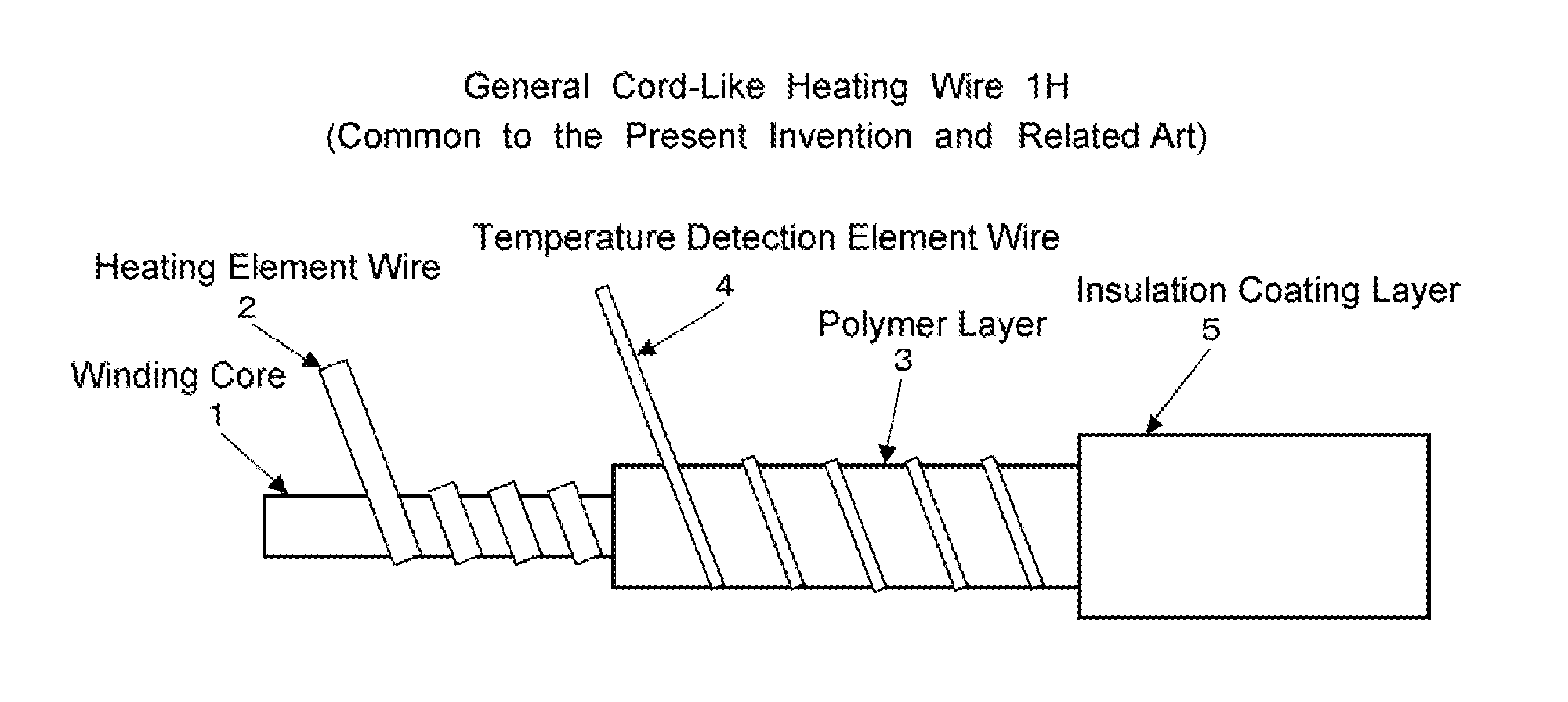
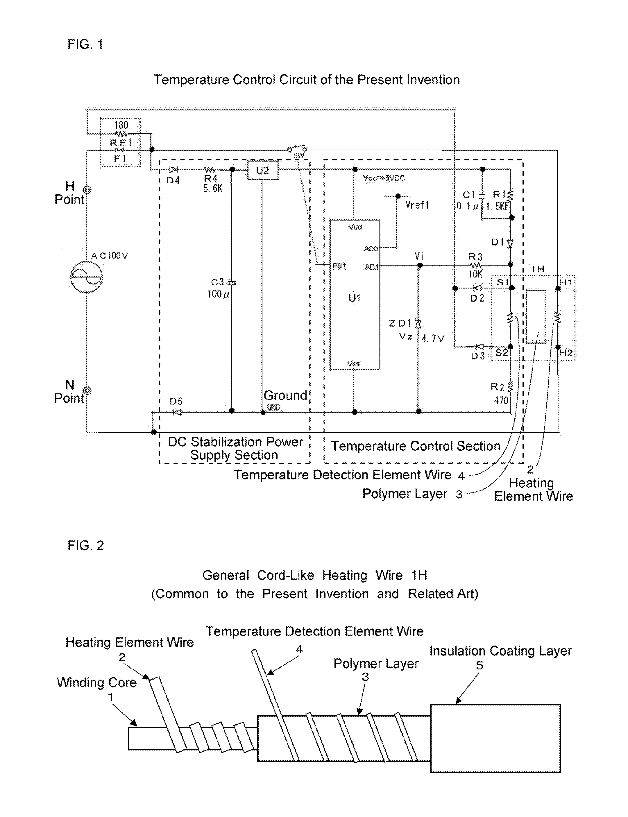
[0053]FIG. 2 is a diagram showing one end of a cord-like heating wire 1H according to an embodiment of the present invention, wherein an insulation coating layer, a polymer layer and the like are partially omitted, and the cord-like heating wire 1H has the same configuration as described in the above-described related art.

[0054]The cord-like heating wire 1H includes a winding core 1 composed of a fiber bundle of glass fiber, polyester fiber or the like, a heating element wire 2 composed of a rectangular conductor which is made of copper or a copper alloy and twisted on the outer periphery of the winding core 1 in a spiral manner, a polymer layer 3 formed by extruding a polymer resin onto the ...


PUM


Abstract

To provide a warming temperature control device which prevents overheating with high accuracy and stability to ensure safety and is excellent in economy, between both electrodes of a DC stabilization power supply which drives a temperature control section, a fixed resistor with which a capacitor is connected in parallel, a first diode disposed in a forward direction with respect to the power supply, and a temperature detection element wire are connected in series, and an inter-wire short circuit protection circuit is included. A degree of leak of a polymer layer is determined by detecting a difference between a maximum value and a minimum value of an input signal to the temperature control section on a time axis. When the difference increases to reach a predetermined set value, the temperature control section performs control such that a heating signal is not outputted.

Description

FIELD OF THE INVENTION[0001]The present invention relates to a warming temperature control device for use in a planar warming apparatus such as an electric blanket or an electric carpet.BACKGROUND OF THE INVENTION[0002]In general, a cord-like heating wire for use in a planar warming apparatus such as an electric blanket or an electric carpet has been hitherto well known. In particular, a cord-like heating wire used frequently in recent years has a configuration called a single-wire type cord-like heating wire in which a heating element wire and a detection element wire are integrated with each other, and the structure thereof is shown in FIG. 2.[0003]The single-wire type cord-like heating wire 1H shown in FIG. 2 includes a winding core 1 composed of a fiber bundle of a polyester fiber or the like, a heating element wire 2 composed of a conductor which is made of copper or a copper alloy and twisted on the outer periphery of the winding core 1 in a spiral manner, a polymer layer 3 fo...

Claims


Application Information

Patent Timeline
Patent Type & Authority Applications(United States)
IPC IPC(8): H05B1/02H05B3/36
CPCH05B1/0252H05B3/10H05B3/56H05B1/0272H05B2203/026H05B1/0205H05B3/36
Inventor NOMURA, TAKASHIASAKURA, MASAHIRO
Owner HONGKONG TACHIBANA ELECTRONICS
Why Eureka
Try Eureka