Sealed compressor and refrigeration device

Active Publication Date: 2017-01-12
PANASONIC APPLIANCES REFRIGERATION DEVICES SINGAPORE
View PDF0 Cites 7 Cited by
  • Summary
  • Abstract
  • Description
  • Claims
  • Application Information

AI Technical Summary

Benefits of technology

[0014]With such a configuration, even when an inner peripheral surface of the bearing at the position where the stator is fixed is deformed at the time of fixing the stator to the outer peripheral portion of the bearing, the non-sliding portion is provided between the main shaft and the bearing at the

Problems solved by technology

Accordingly, the conventional sealed compressor has a drawback that an inner peripheral surface of bearing 410 at the position where stator 420 is fixed is deformed and hence, soli

Method used


Image

  • Sealed compressor and refrigeration device
  • Sealed compressor and refrigeration device
  • Sealed compressor and refrigeration device

Examples


Example

First Exemplary Embodiment

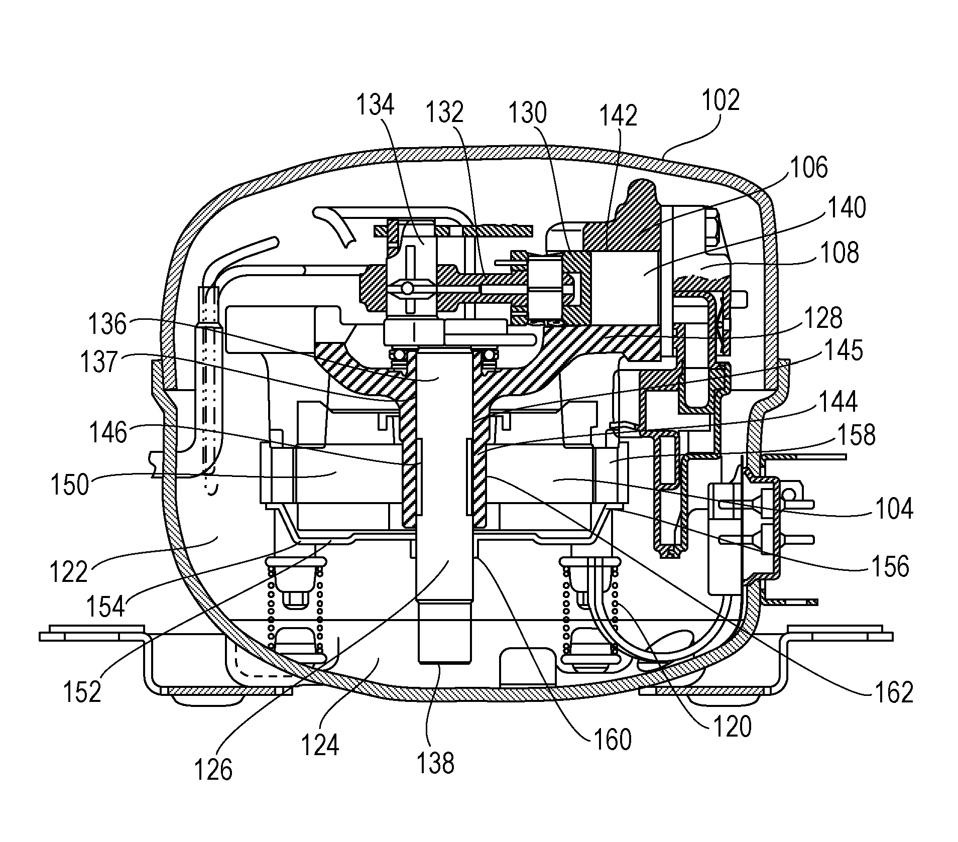
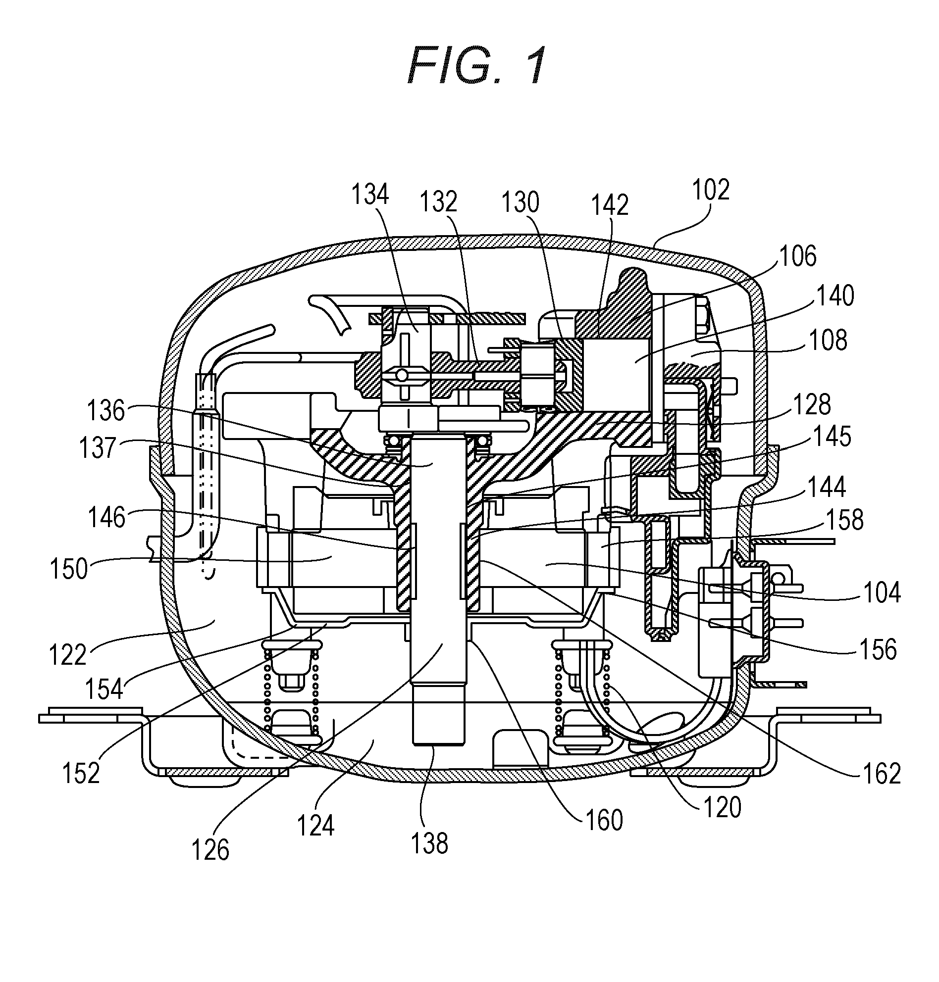
[0022]FIG. 1 is a cross-sectional view of a sealed compressor according to a first exemplary embodiment of the present invention. FIG. 2 is a cross-sectional view showing a main part of the sealed compressor.

[0023]In FIG. 1, the sealed compressor according to this exemplary embodiment is configured such that compressor body 108 which includes electrically-operated element 104 and compressive element 106 driven by electrically-operated element 104 is disposed in the inside of sealed container 102 formed by drawing a steel plate.

[0024]Compressor body 108 is resiliently supported by suspension springs 120.

[0025]Sealed container 102 is filled with refrigerant gas 122 which is at a pressure substantially equal to a pressure on a low-pressure side of a refrigeration device (not shown in the drawing) and in a relatively low temperature state. For example, refrigerant gas 122 is R600a which is a hydrocarbon refrigerant having a low global warming potential. A botto...

Example

Second Exemplary Embodiment

[0048]FIG. 3 is a cross-sectional view showing a main part of a sealed compressor according to a second exemplary embodiment of the present invention. In this exemplary embodiment, parts identical with the parts of the first exemplary embodiment are given the same symbols and the description of those parts is omitted.

[0049]In the case of this exemplary embodiment, non-sliding portion 246 is formed on a bearing 244 side. That is, non-sliding portion 246 formed by increasing an inner diameter of bearing 244 is formed on a portion of a sliding portion of bearing 244. More specifically, considering “a solid contact which occurs between the bearing and the main shaft” and “supply of oil”, it is preferable that a size of non-sliding portion 246 in a radial direction which is formed on the portion of the sliding portion of bearing 244 by increasing an inner diameter of bearing 244 be preferably set between 0.2 mm and 1.0 mm (both inclusive). When the size in a ra...

Example

Third Exemplary Embodiment

[0052]FIG. 4 is a schematic view showing a refrigeration device according to a third exemplary embodiment of the present invention. The sealed compressor described in the first or second exemplary embodiment is mounted in the refrigeration device. In this exemplary embodiment, the refrigeration device is schematically described by taking an article storage device such as a refrigerator as an example.

[0053]In FIG. 4, the article storage device includes body 302 which is formed of a heat insulating box having an opening on one surface thereof and a door body which opens and closes the opening; partition wall 308; and refrigerant circuit 310. Partition wall 308 partitions the inside of body 302 into article storage space 304 and machine compartment 306. Refrigerant circuit 310 cools storage space 304.

[0054]Refrigerant circuit 310 is configured such that the sealed compressor described in the first exemplary embodiment which forms compressor 312, heat-radiator ...


PUM


Abstract

In a sealed compressor, electrically-operated element (104) and compressive element (106) driven by electrically-operated element (104) are housed in the inside of sealed container (102). Compressive element (106) includes shaft (126) formed of main shaft (136) and eccentric shaft (134), and cylinder block (128) having; bearing (144) which pivotally supports main shaft (136) of shaft (126); and cylinder (142). Further, the compressive element (106) includes piston (130) which is movable in the cylinder (142) in a reciprocating manner, and connecting portion (132) which connects eccentric shaft (134) and piston (130) to each other. Electrically-operated element (104) is formed of an outer-rotor-type motor which includes stator (150), and rotor (152) which is disposed coaxially with stator (150) so as to surround an outer periphery of stator (150). Further, non-sliding portion (146) is provided between main shaft (136) and bearing (144), and stator (150) is fixed to outer peripheral portion (162) of bearing (144) which corresponds to non-sliding portion (146).

Description

TECHNICAL FIELD[0001]The present invention relates to a sealed compressor and a refrigeration device such as a household-use electric freezer refrigerator or a showcase in which the sealed compressor is mounted.BACKGROUND ART[0002]Recently, along with diversification of food materials, a demand for the increase of a capacity of an indoor volume of a refrigeration device such as a household-use electric freezer refrigerator is increasing. To cope with such a demand, improvement has been made to increase capacity of a household-use electric refrigerator while maintaining a size of an external appearance of the household-use electric refrigerator. As one of methods for increasing the indoor volume, the reduction in size of a machine compartment which houses a sealed compressor has been in progress. In the sealed compressor used in the household-use electric freezer refrigerator, other refrigeration cycle devices and the like, the miniaturization and the reduction in height of the seale...

Claims


Application Information

Patent Timeline
IPC IPC(8): F04B35/04F25B1/02F25D11/00F25D23/00F04B39/00F04B39/12
CPCF04B35/04F04B39/0005F04B39/122F25D2500/02F25D23/006F25B1/02F25D11/00F04B39/00F04B39/023F25B31/023F25D17/062F25D2317/0665
Inventor YANASE, SEIGO
Owner PANASONIC APPLIANCES REFRIGERATION DEVICES SINGAPORE
Why Eureka
Try Eureka