Vibration Damper Having An End Stop

a technology of vibration damper and end stop, which is applied in the direction of vibration damper, liquid based damper, shock absorber, etc., can solve the problems of increasing the friction of the end stop and the installation space, and achieve the effect of high mechanical strength and easy production

Inactive Publication Date: 2017-01-12
ZF FRIEDRICHSHAFEN AG
View PDF0 Cites 24 Cited by
  • Summary
  • Abstract
  • Description
  • Claims
  • Application Information

AI Technical Summary

Benefits of technology

[0016]A particularly advantageous embodiment is characterized in that the at least one axial pocket extends through an end face facing in direction o...

Problems solved by technology

However, a drawback remained in the possibly greater radial preloading of the choke ring, which increases the fr...

Method used


Image

  • Vibration Damper Having An End Stop
  • Vibration Damper Having An End Stop
  • Vibration Damper Having An End Stop

Examples


Embodiment Construction

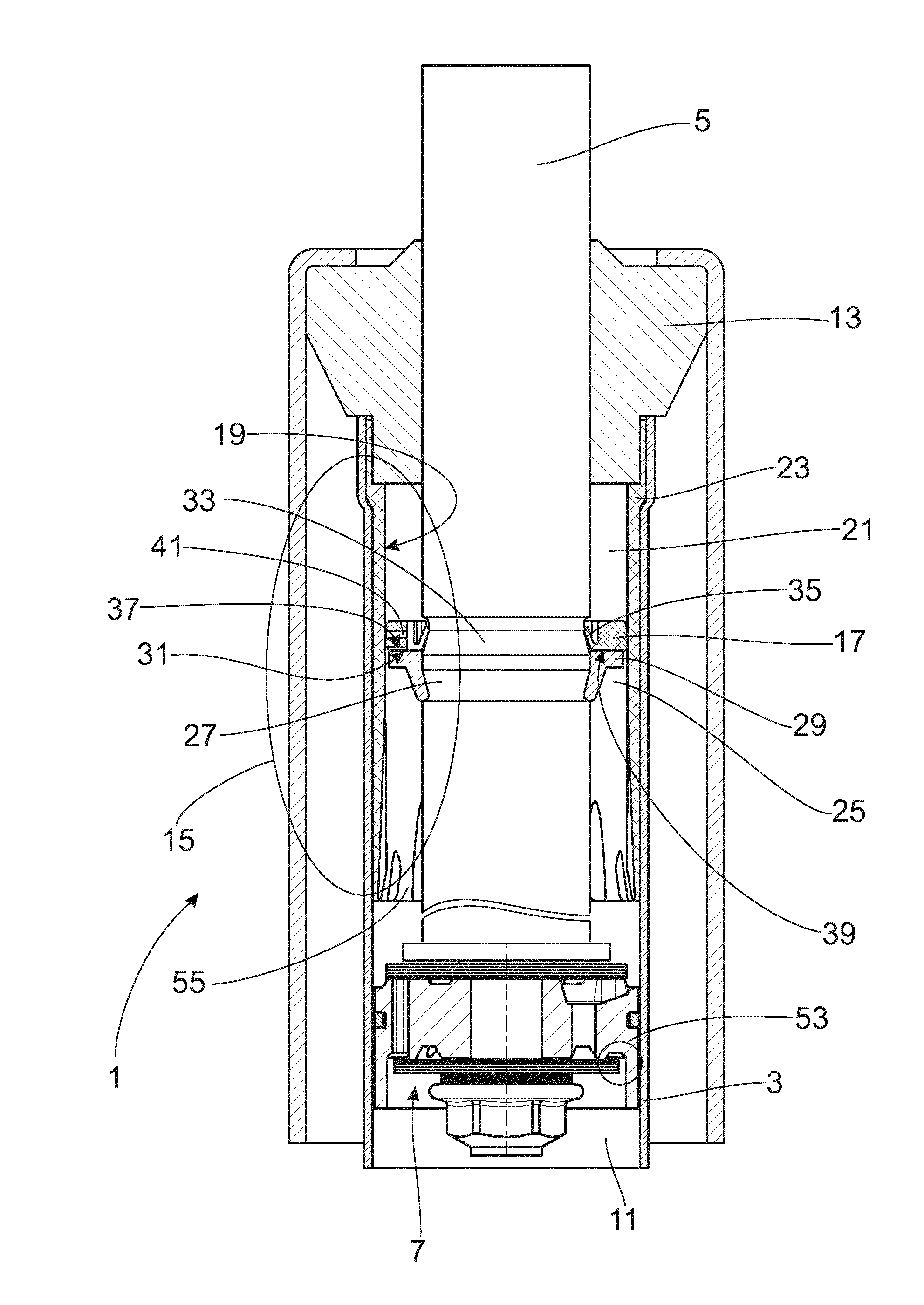
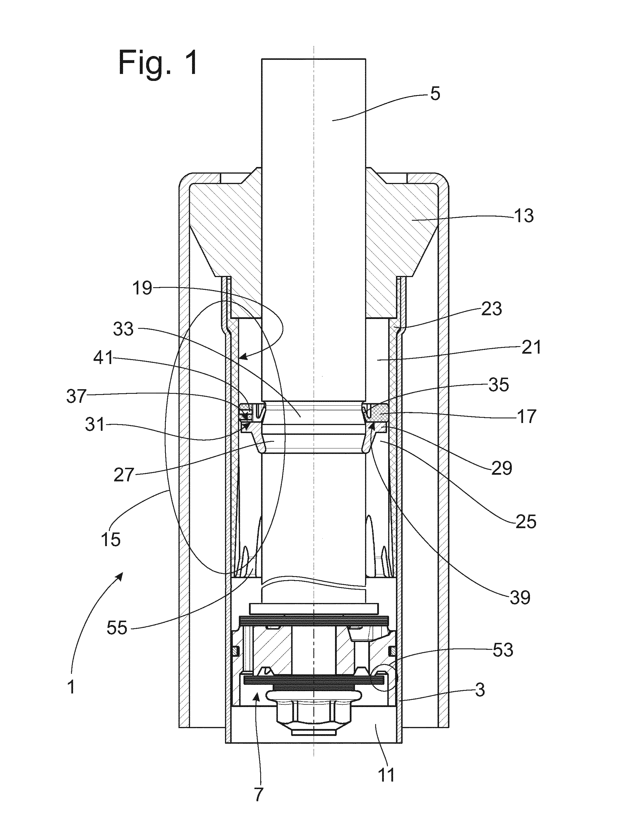
[0022]FIG. 1 shows a vibration damper 1 in the constructional form of a twin-tube damper, although the invention is not limited to this constructional form. A piston rod 5 together with a piston 7 is guided in a cylinder 3 so as to be axially movable. The cylinder 3 is divided by the piston 7 into a working chamber 9 proximal to the piston rod and a working chamber 11 distal to the piston rod. Both working chambers 9; 11 are completely filled with a damping medium, generally a liquid damping medium. At the ends, the vibration damper in its entirety is closed by a piston rod guide 13. An end stop 15 which is operated by damping medium inside the cylinder 3 is arranged in the working chamber 9 proximal to the piston rod 5. In principle, an end stop 15 of this kind can also be provided in the working chamber 11 distal to the piston rod 5.

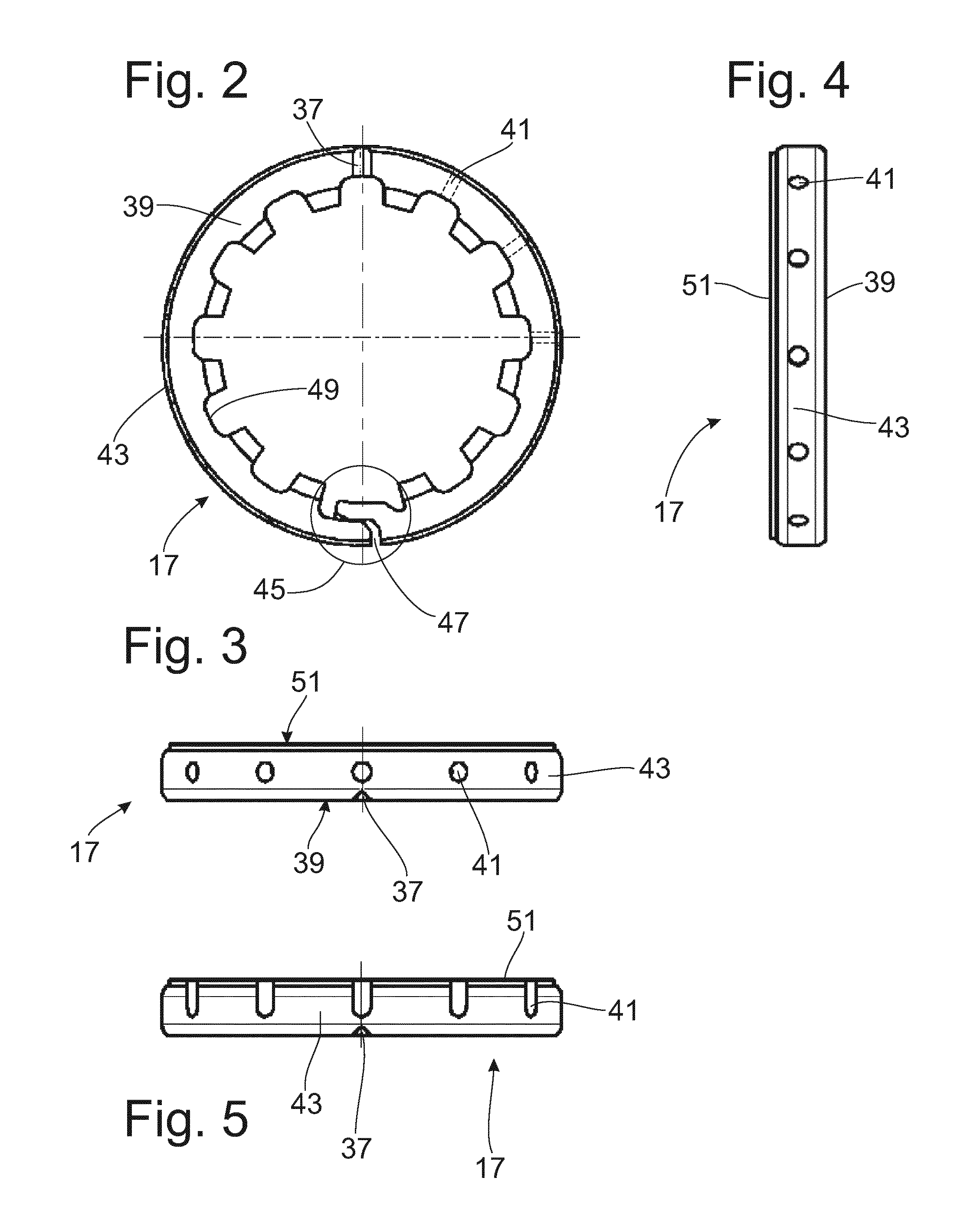
[0023]The end stop 15 comprises a choke ring 17 which is supported at the piston rod 5 and which limits a compression space 21 starting from a defined...


PUM


Abstract

Vibration damper with an end stop operated through a damping medium, includes a cylinder in which a piston rod is guided so as to be axially movable, wherein the piston rod controls a choke ring which limits a compression space starting from a defined stroke position of the piston rod at a cylinder-side wall having reduced diameter, wherein the cylinder has at least one working chamber which is filled with the damping medium and which is connected to the compression space via at least one choke orifice, wherein the choke ring has at least one pressure compensation channel via which a surface of the choke ring facing in direction of the wall on the cylinder side is connected to compression space with respect to the cross section of the choke ring, and the outflow from the pressure compensation channel to the working chamber can be closed in a stroke-dependent manner.

Description

PRIORITY CLAIM[0001]This is a U.S. national stage of application No. PCT / EP2015 / 051568, filed on Jan. 27, 2015. Priority is claimed on the following application: Country: Germany, Application No.: 10 2014 203 598.8, Filed: Feb. 27, 2014 ,the content of which is incorporated in its entirety herein by reference.FIELD OF THE INVENTION[0002]The invention is directed to a vibration damper with an end stop.BACKGROUND OF THE INVENTION[0003]In a vibration damper with a hydraulic end stop known from US2014 / 360353A1, an end stop ring on which a choke ring is axially supported is fastened to a piston rod. The choke ring is radially preloaded and seals starting from a defined stroke position at a cylinder wall having a reduced diameter. The cylinder wall can be formed by a sleeve which is separate from the cylinder or directly by the cylinder.[0004]However, when the choke ring seals at the outer circumference, a choke cross section is opened through which damping medium is displaced from an end...

Claims


Application Information

Patent Timeline
IPC IPC(8): F16F9/49F16F9/19
CPCF16F9/19F16F9/49F16F2222/12
Inventor HERTZ, WOLFGANG
Owner ZF FRIEDRICHSHAFEN AG
Why Eureka
Try Eureka