Combustor

a gas turbine engine and combustion chamber technology, applied in the direction of machines/engines, mechanical equipment, lighting and heating apparatus, etc., can solve the problems of poor starting reliability, difficult to achieve this with liquid fuel, and difficult to maintain flame stability. good, the effect of starting reliability

Inactive Publication Date: 2017-01-12
SIEMENS ENERGY GLOBAL GMBH & CO KG
View PDF21 Cites 4 Cited by
  • Summary
  • Abstract
  • Description
  • Claims
  • Application Information

AI Technical Summary

Benefits of technology

[0013]The objective of the present invention is to provide a combustor for a g

Problems solved by technology

Nevertheless, these lean fuel to air ratios are problematic with respect to maintaining flame stability when the engine load is reduced.
In particular if such a combustor is run on liquid fuel a poo

Method used


Image

  • Combustor
  • Combustor
  • Combustor

Examples


Embodiment Construction

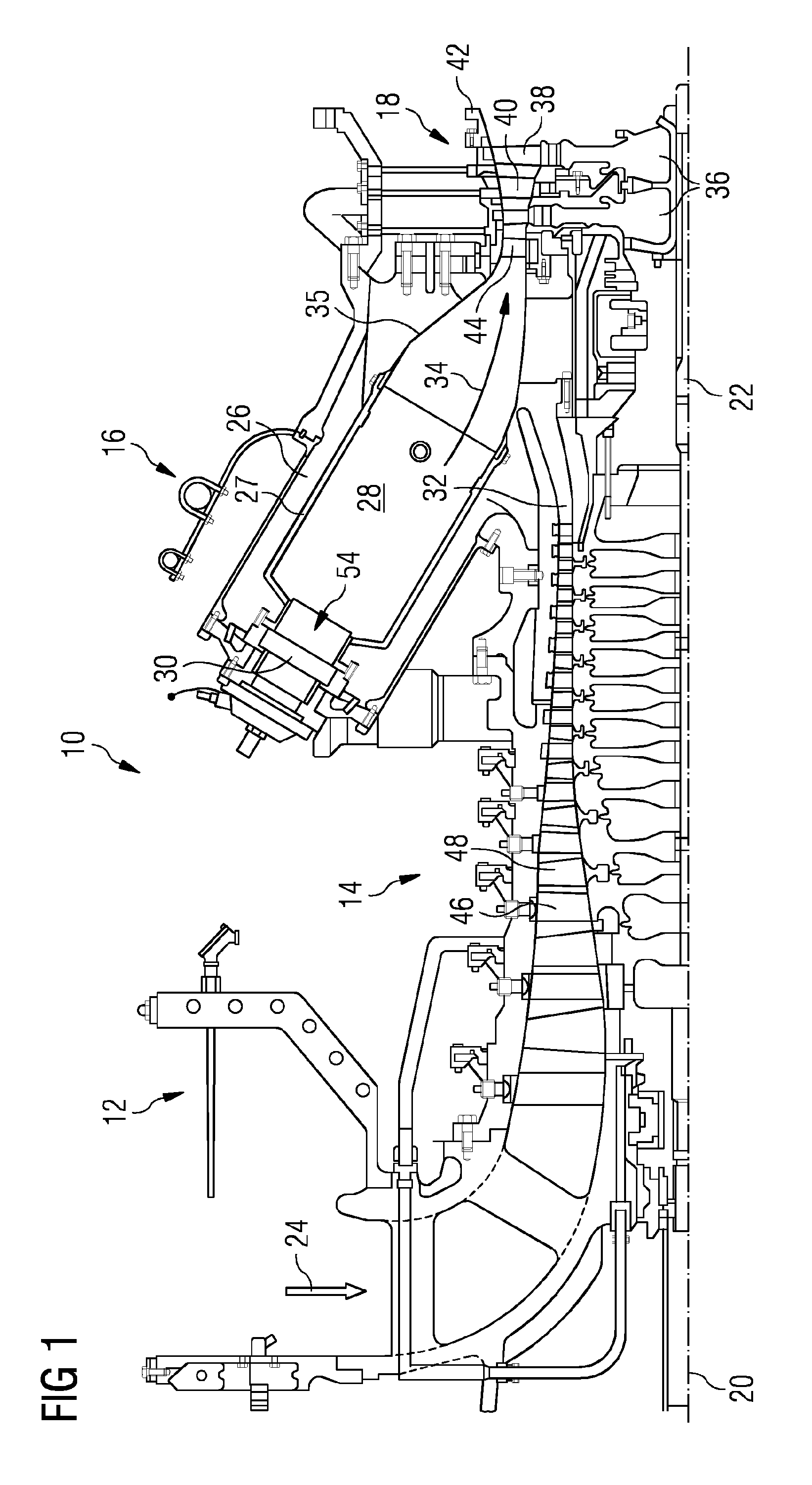
[0032]The terms upstream and downstream refer to the flow direction of the air and / or combustion gas through the gas turbine engine unless otherwise stated. The terms forward and rearward refer to the general flow of gas through the gas turbine engine. The terms axial, radial and circumferential are made with reference to a rotational axis 20 of the gas turbine engine if not stated otherwise.

[0033]FIG. 1 shows an example of a gas turbine engine 10 according to the invention in a sectional view. The gas turbine engine 10 comprises, in flow series, an air inlet 12, a compressor section 14, a combustor section 16 and a turbine section 18, which are generally arranged in flow series and generally in the direction of the rotational axis 20 (which is also the longitudinal axis of the gas turbine engine 10). The gas turbine engine 10 further comprises a shaft 22, which is rotatable about the rotational axis 20 and which extends longitudinally through the gas turbine engine 10. The shaft 22...


PUM


Abstract

A burner includes a pilot burner, a combustion chamber, and a swirler located radially outwardly of the combustion chamber and being adapted to impose a swirling motion on a fuel/air mixture about an axial centerline of the combustion chamber. The pilot burner has a pilot burner face located radially inwardly of the swirler and forms an axially upstream wall of the combustion chamber, the pilot burner face incorporating a pilot fuel injector and an ignitor, both being positioned radially offset from the axial centerline. A recess is positioned radially offset from the axial centerline within the pilot burner face.

Description

CROSS REFERENCE TO RELATED APPLICATIONS[0001]This application is the US National Stage of International Application No. PCT / EP2015 / 050104 filed Jan. 6, 2015, and claims the benefit thereof. The International Application claims the benefit of European Application No. EP14154207 filed Feb. 6, 2014. All of the applications are incorporated by reference herein in their entirety.FIELD OF INVENTION[0002]The present invention is directed to a combustor and to a gas turbine engine comprising such a combustor.BACKGROUND OF INVENTION[0003]A typical gas turbine engine comprises an air inlet followed by a compressor section in which incoming air is compressed for application to one or more combustors of a combustor section of the gas turbine engine. A fuel, which may be a gaseous or liquid fuel, is introduced into the combustors and mixed with a part of the compressed air. Hot combustion gas created by combustion of the fuel / air mixture in the combustors is directed to a turbine section compris...

Claims


Application Information

Patent Timeline
IPC IPC(8): F23R3/28F02C7/264F23R3/14
CPCF23R3/286F23R3/14F05D2240/35F05D2220/32F02C7/264F23C7/004F23C2900/07001F23Q3/008F23R3/343
Inventor BUCHANAN, EOGHANSADASIVUNI, SURESH
Owner SIEMENS ENERGY GLOBAL GMBH & CO KG
Why Eureka
Try Eureka