Wireless IC device, clip-shaped RFID tag, and article having RFID tag

a technology of ic device and rfid tag, which is applied in the direction of resonant antenna, elongated active element feed, instruments, etc., can solve the problems of inability to perform read/write of the tag, inability to ensure a sufficient communication distance, and inconvenient use, so as to improve the robustness of the wireless ic device, increase the current flowing through the metal body, and improve the effect of the gain

Active Publication Date: 2017-01-19
MURATA MFG CO LTD
View PDF15 Cites 3 Cited by
  • Summary
  • Abstract
  • Description
  • Claims
  • Application Information

AI Technical Summary

Benefits of technology

[0022]A current flowing through the loop conductor is maximized in the vicinity of a loop end. Therefore, when the loop conductor and the object are connected, connecting the connection conductor in the vicinity of the loop end maximizes the current flowing through the metal body of the object and therefore improves the gain. By disposing the loop conductor on the object such that the loop surface is along the surface of the object, the robustness of the wireless IC device is improved.
[0023]A current amount (current density) flowing through the loop conductor is maximized in the vicinity of a loop end. Therefore, when the loop conductor and the clip is connected, connecting the connection conductor in the vicinity of the loop end maximizes the current amount flowing through the clip and therefore maximizes the current amount flowing through the conductor of the article to which the clip is attached. The conductor of the article defines and functions as a radiator or a radiation element, so that a high gain is produced. As a result, the communication characteristics are improved.

Problems solved by technology

If an RFID tag utilizing the UHF band for wireless communications is directly affixed to a metal body, an electric field component of radio waves transmitted from a reader / writer becomes zero on a surface of the tag, making it unable to perform read / write of the tag.
However, the structure of WO 2009 / 008296 including an RFID tag affixed with a loop surface perpendicular to a metal surface causes the RFID tag to project from the metal body and therefore is not suitable for a use particularly requiring robustness of a tag (e.g., for a gas cylinder).
However, if the object is a conductor, i.e., if the clip is attached to a conductor, the technique of JP 2004-192287 A or JP 2004-307209 A has a problem of not being able to ensure a sufficient communication distance because the conductor impairs the communication characteristics (particularly, the gain) of the RFID tag.

Method used


Image

  • Wireless IC device, clip-shaped RFID tag, and article having RFID tag
  • Wireless IC device, clip-shaped RFID tag, and article having RFID tag
  • Wireless IC device, clip-shaped RFID tag, and article having RFID tag

Examples


first preferred embodiment

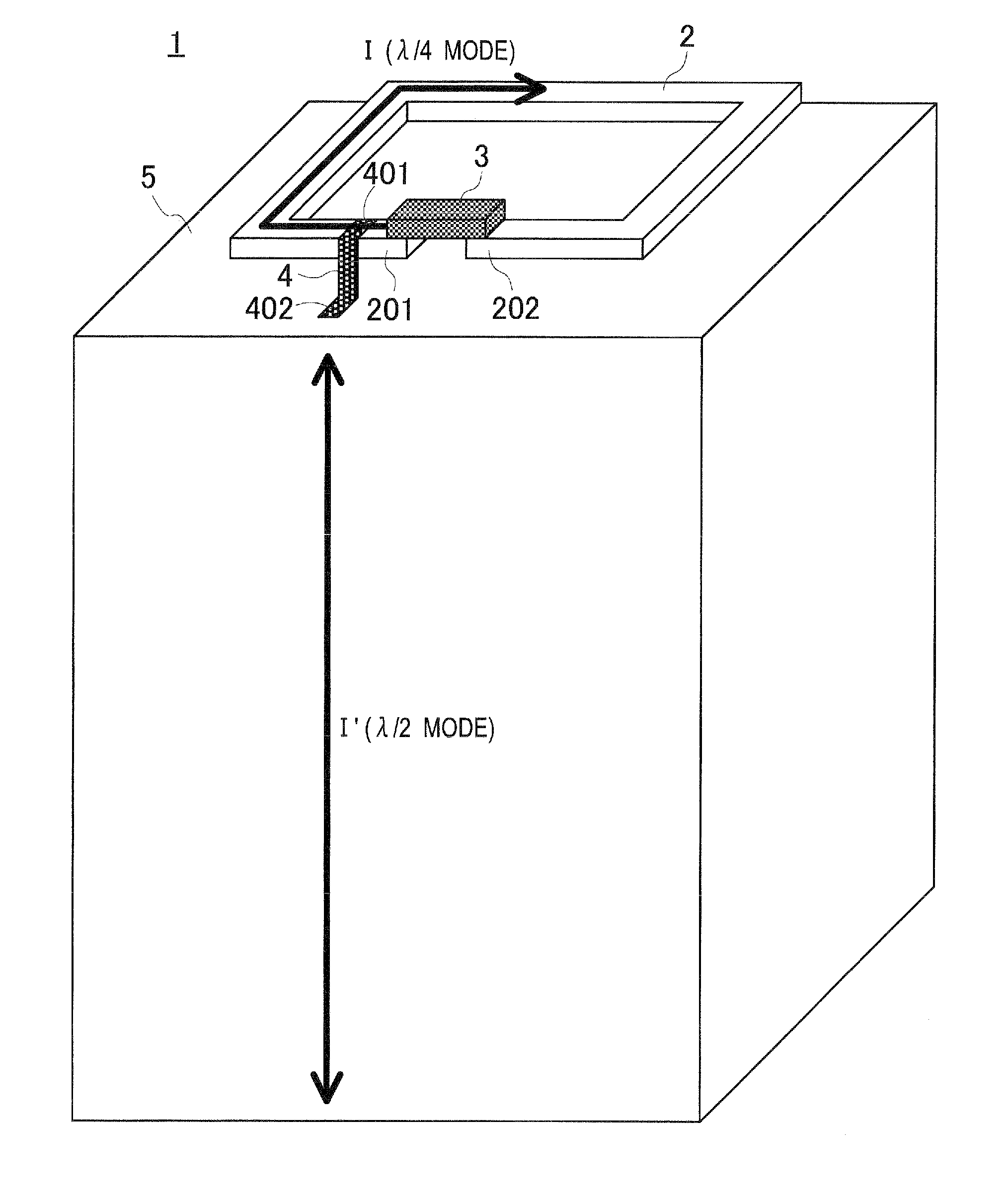
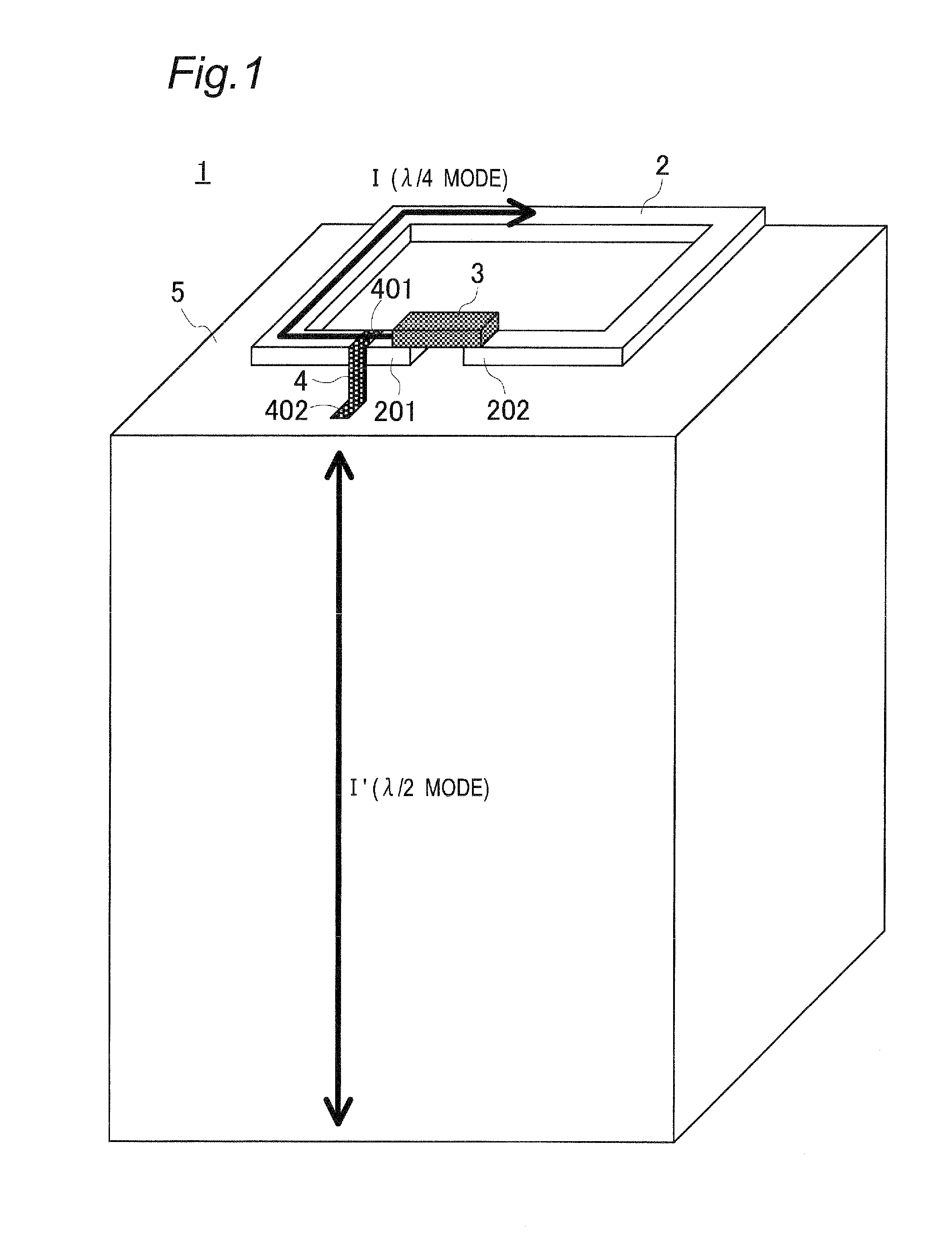
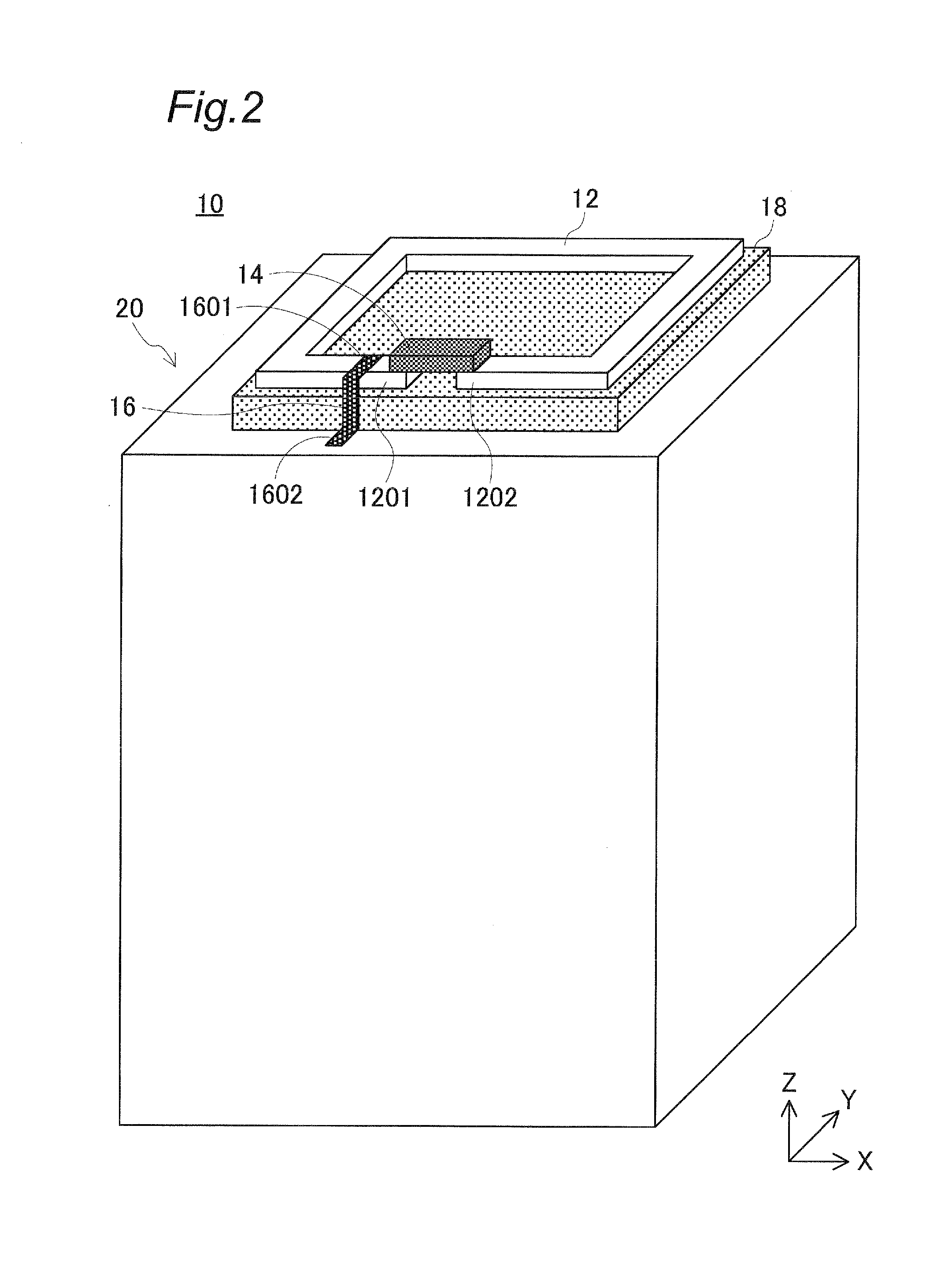
[0052]Referring to FIGS. 2 and 3, a wireless IC device 10 of a first preferred embodiment of the present invention includes a loop-shaped antenna conductor 12, a rectangular or substantially rectangular parallelepiped RFIC element 14, a belt-shaped connection conductor 16, an insulating pedestal (spacer) 18 defining a flat plate, and a rectangular or substantially rectangular columnar body 20. In the first preferred embodiment, an X-axis, a Y-axis, and a Z-axis are assigned to a width direction, a depth direction, and a height direction, respectively, of the columnar body 20.

[0053]The pedestal 18 includes a principal surface smaller than an upper surface of the columnar body 20 and is placed in a posture with the principal surface perpendicular or substantially perpendicular to the Z-axis on the center of the upper surface of the columnar body 20. The antenna conductor 12 has a loop surface smaller than the principal surface of the pedestal 18 and is placed in a posture with the loo...

second preferred embodiment

[0069]Referring to FIGS. 8 and 9, a wireless IC device 10a of a second preferred embodiment of the present invention preferably includes an antenna conductor 32, the RFIC element 14, and a circular columnar body 30.

[0070]The antenna conductor 32 is a conductor including a loop portion (loop conductor) 321p, a leg portion (portion of a connection conductor) 321g, and a fixing portion (another portion of the connection conductor) 32fx integrally formed. As described later in detail, the antenna conductor 32 is produced preferably by punching and bending of a hoop material. As a result, a principal surface of the loop portion 321p and a principal surface of the fixing portion 32fx spread in parallel or substantially in parallel with each other, and a principal surface of the leg portion 321g extends perpendicularly or substantially perpendicularly to the principal surface of the loop portion 321p or the fixing portion 32fx.

[0071]The loop portion 321p includes one end (a first loop end...

third preferred embodiment

[0085]Referring to FIGS. 12A, 12B, 13, and 14, a clip-shaped RFID tag 100 of a third preferred embodiment of the present invention preferably is an RFID tag using the 900 MHz band as a communication frequency and includes a crocodile clip 120, a lead wire 140, an RFIC element 180, and a loop conductor 220.

[0086]The crocodile clip 120 includes conductive clip pieces 121 and 122. A serrated locking portion 121t is provided on an inside surface of a tip of the clip piece 121, and a serrated locking portion 122t is provided on an inside surface of a tip of the clip piece 122. The length of the clip piece 122 exceeds the length of the clip piece 121, and a retainer 124 (described later in detail) retaining the lead wire 140 is provided at a base end of the clip piece 122.

[0087]The clip pieces 121 and 122 are supported by a conductive shaft (supporting member) 123 such that the locking portions 121t and 122t engage with each other, and are made swingable in the rotation direction of the s...


PUM


Abstract

In a wireless IC device, a columnar body includes a metal body with an insulating film. A loop-shaped antenna conductor is provided on an upper surface of the columnar body via an insulating pedestal. The loop surface of the antenna conductor is parallel or substantially parallel to the upper surface of the columnar body. On the lower surface of a RFIC element, two terminal electrodes are provided. The RFIC element is mounted on the antenna conductor such that the two terminal electrodes are connected to both ends of the antenna conductor, respectively. One end of the connecting conductor is connected to the vicinity of one end of the antenna conductor, and the other end of the connecting conductor is connected to the upper surface of the columnar body.

Description

CROSS REFERENCE TO RELATED APPLICATIONS[0001]This application claims the benefit of priority to Japanese Patent Application No. 2014-092643 filed on Apr. 28, 2014, Japanese Patent Application No. 2014-126813 filed on Jun. 20, 2014 and Japanese Patent Application No. 2014-222167 filed on Oct. 31, 2014 and is a Continuation application of PCT Application No. PCT / JP2015 / 062030 filed on Apr. 21, 2015. The entire contents of each application are hereby incorporated herein by reference.BACKGROUND OF THE INVENTION[0002]1. Field of the Invention[0003]The present invention relates to a wireless IC device and to a wireless IC device in which an RFIC (radio frequency integrated circuit) element is mounted on an object including a metal body. The present invention also relates to a clip-shaped RFID (radio frequency identifier) tag and to a clip-shaped RFID tag attachable to and detachable from a conductor of an article. The present invention further relates to an article including an RFID tag s...

Claims


Application Information

Patent Timeline
Patent Type & Authority Applications(United States)
IPC IPC(8): G06K19/04G06K19/077
CPCG06K19/077G06K19/04G06K19/07758G06K19/07771G06K19/07786G06K19/0779H01Q1/2208H01Q7/00H01Q9/42H01Q5/371
Inventor KOMAKI, KUNIHIRO
Owner MURATA MFG CO LTD
Why Eureka
Try Eureka