Image intensifier with indexed compliant anode assembly

an image intensifier and compliant technology, applied in the direction of discharge tube main electrodes, photo-emissive cathodes, tubes with screens, etc., can solve the problems of affecting the performance of image intensifiers, and raising production costs for these components, so as to achieve high performance, low cost, and high performance.

Active Publication Date: 2017-01-19
EOTECH LLC
View PDF1 Cites 2 Cited by
  • Summary
  • Abstract
  • Description
  • Claims
  • Application Information

AI Technical Summary

Benefits of technology

[0010]Disclosed embodiments facilitate a low cost approach to achieve highly accurate cathode to anode assembly dimensional control (<10 micron accuracy) in order to fabricate consistent, high performance, proximity focused image intensifiers. The embodiments include insulating spacers affixed to the surface of the anode assembly that faces the photocathode. Further embodiments give the sensor designer a mechanism by which they can engineer the anode compliance versus force behavior to meet both the mechanical tolerance budget associated with cost-effective sensor components and the minimum required anode assembly to cathode assembly force required to insure that the finished sensor is reliable when exposed to required shock and vibration environments.
[0011]Disclosed embodiments include a spring support structure that mounts the anode assembly to the vacuum package assembly. Consequently, the anode is flexibly attached to the packaging. A high stiffness is achieved in the spring support structure to displacements lateral to the direction of the applied spring force. Disclosed embodiments achieve the force versus displacement goals while adding the minimum required size and weight to the image intensifier.
[0012]Disclosed embodiments also achieve good heat transfer from the anode assembly to the vacuum package assembly and reliably achieve low leakage currents (<10 nA) between the photocathode assembly and the anode assemble when a high voltage bias (typically ˜−1200V) is applied between the photocathode and the anode assembly when the sensor is in a dark environment.
[0013]Further embodiments limit the force applied by the spring to the photocathode to a moderate level in order to maintain the reliability of the photocathode to vacuum package, vacuum seal. Disclosed embodiments provide a sufficiently high effective spring constant for the anode assembly such that commercially available wire-bond equipment can generate reliable wire-bonds from the compliant anode assembly to bond pads on an inner surface of the vacuum package.
[0014]According to disclosed embodiments, the presence of any molten brazes or solders is eliminated from the image intensifier components at the time of the creation of the vacuum seal. Also, disclosed aspects keep the un-sprung anode assembly weight to a minimum so as to minimize the spring force required to keep anode assembly stationary with respect to the photocathode assembly within a required shock and vibration environment.
[0015]Disclosed aspects employ a spacer design that spreads the compressive load associated with the spring over a sufficiently large area of the photocathode assembly to avoid damage to the photocathode assembly at the points of contact.

Problems solved by technology

This spreading results in a loss of image sharpness.
Increased photocathode dark current adversely affects image intensifier performance when used for night vision applications.
Specifying precise dimensional tolerances for image intensifier components generally raises production costs for these components.
Perhaps the most important of these issues is cost.
The GaAs photoemission surface is quite sensitive to damage and contamination.
Increasing the complexity of the manufacture process and the required handling translates into increased component yield loss and consequently increased cost.
Additionally, Iosue fails to address issues related to the physical compliance of the surface that is contacted by the spacer.
A failure to design in sufficient compliance will potentially result in: low sensor yield (Adds cost), tight geometric specification requirement for sensor components (Adds cost), and inconsistent forces between the photocathode and the opposing surface present the potential for shock / vibration damage and reliability issues particularly when high voltage gated gain control approaches are used.
However, with the exception of U.S. Pat. No. 7,607,560, none of the prior art indirect view image intensifier packaging approaches include compliant anode assemblies which index directly to the photocathode assembly.
This requirement adds image intensifier processing constraints that are undesirable.
Specifically, accurate vacuum temperature control is difficult to accomplish in the hardware required to generate the vacuum seal.
Additionally, any jostling during the vacuum sealing process can result in an uncontrolled displacement of the molten braze / solder material resulting in a non-functional image intensifier.

Method used


Image

  • Image intensifier with indexed compliant anode assembly
  • Image intensifier with indexed compliant anode assembly
  • Image intensifier with indexed compliant anode assembly

Examples


Embodiment Construction

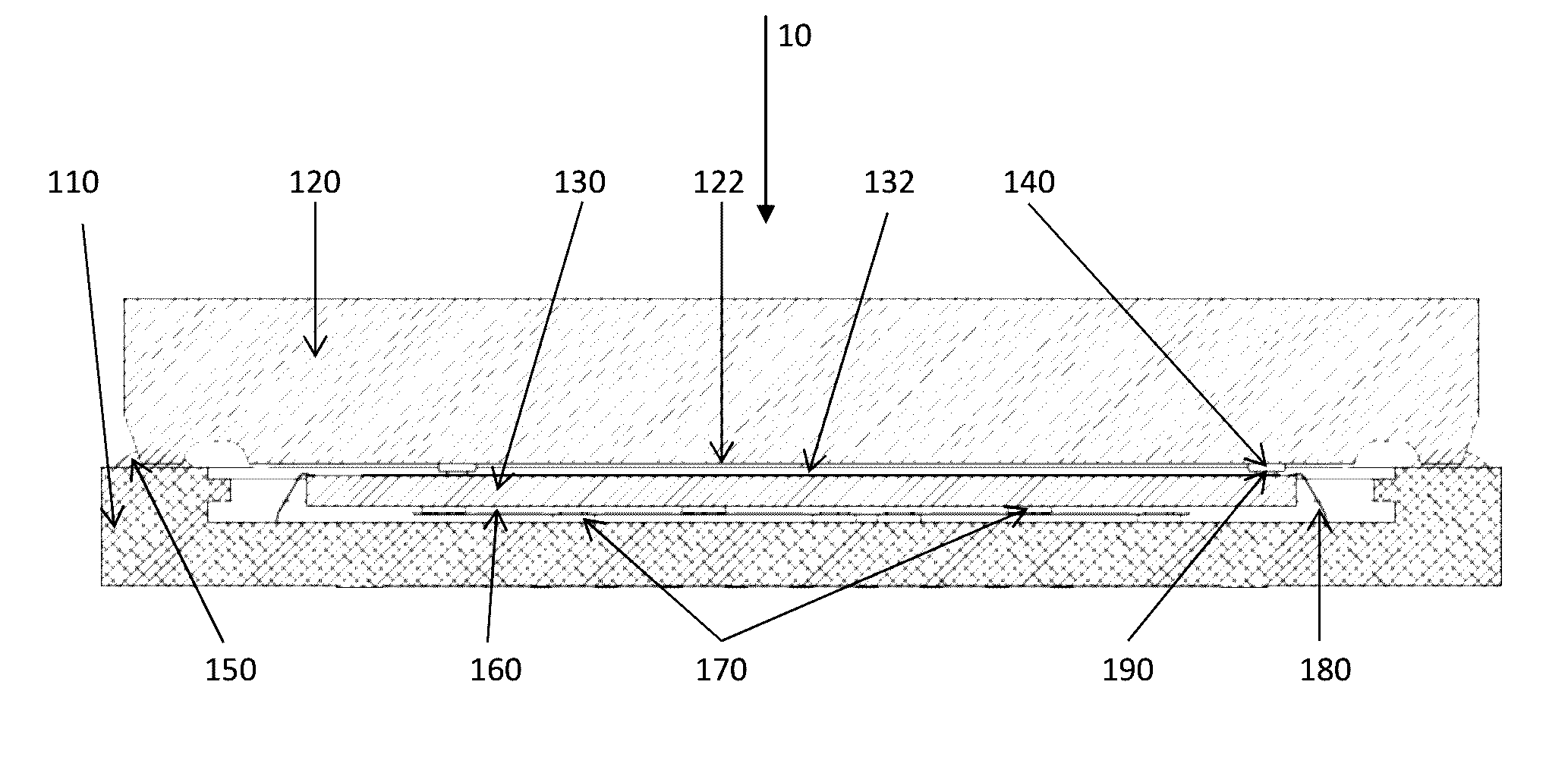
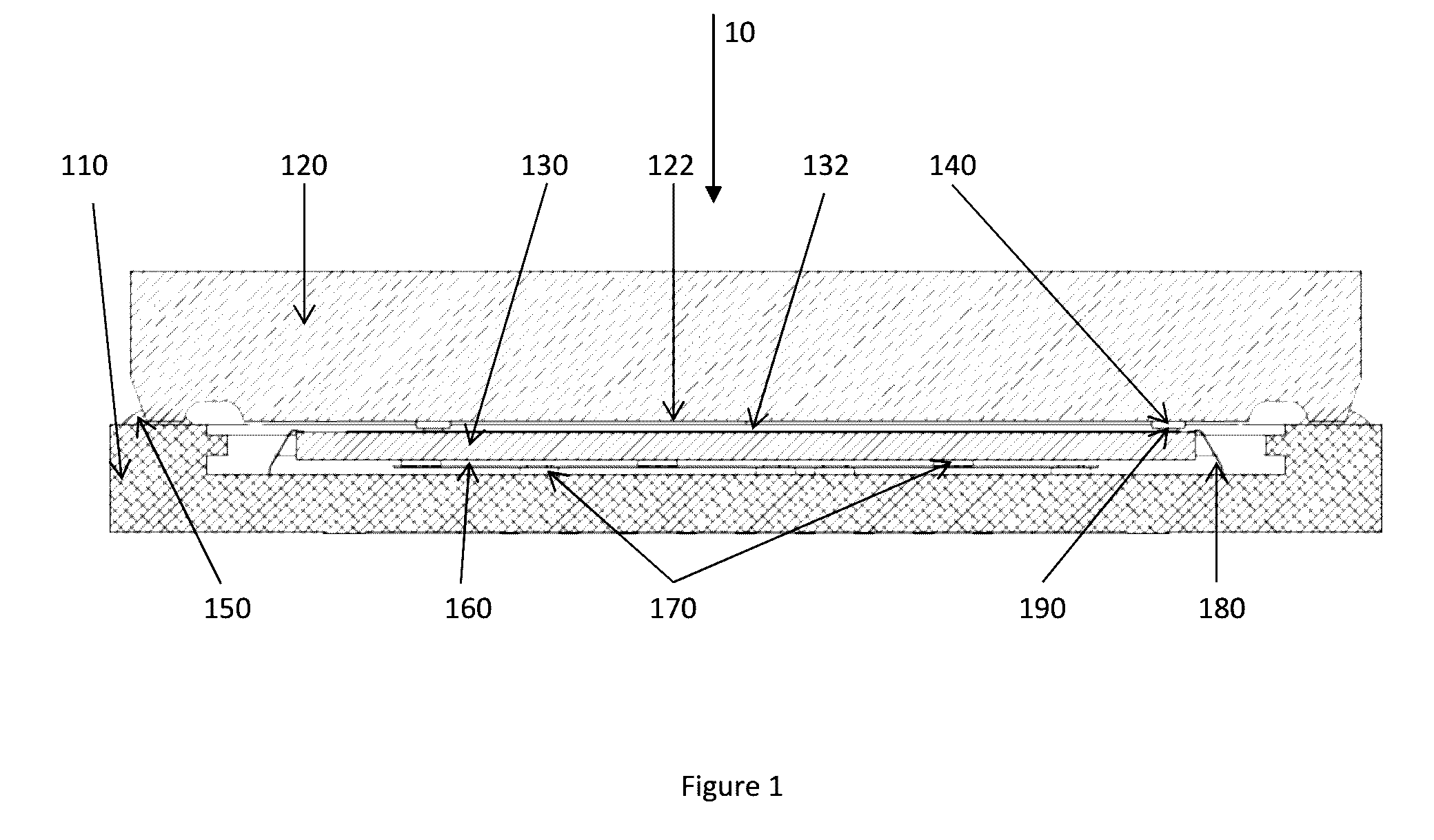
[0034]FIG. 1 shows a cross-sectional view of an EBAPS image intensifier incorporating an exemplary embodiment of the invention. The vacuum package assembly (110) is typically based on a hermetic, multi-layer, high temperature co-fired ceramic package fabricated via conventional means. As shown in FIG. 1, the ceramic package employs a ceramic design protected under the claims of U.S. Pat. No. 6,837,766. As detailed in U.S. Pat. 6,837,766 B2, the non-monotonically varying inner ceramic side wall of the vacuum package increases the high voltage stand-off potential of the wall and therefore improves sensor yield. U.S. Pat 6,837,766 B2 is incorporated by reference. The vacuum package (110) assembly is sealed to a photocathode assembly (120) by means of a sealing material (150) in order to complete a vacuum envelope. The vacuum envelope encloses an anode assembly (130). The photo-emissive portion of the photocathode assembly resides on the inner surface of the assembly (122) facing the el...


PUM


Abstract

An image intensifier and a method of fabrication are disclosed. The image intensifier contains a photocathode assembly (120) including a vacuum window to generate photoelectrons in response to light, a vacuum package (110) and an anode assembly (130) to receive the photoelectrons. The anode assembly is mounted to the vacuum package via a compliant, springy, support structure (160). The anode additionally includes one or more insulating spacers (140) on the surface facing the photocathode so as to precisely index the position of the anode assembly with respect to the photocathode surface. The photocathode and vacuum window assembly is pressed into the vacuum package to generate a sealed leak tight vacuum envelope. During the photocathode assembly to vacuum package assembly pressing operation, the inner surface of the photocathode assembly contacts the insulating spacer/spacers of the anode assembly, thereby compressing the compliant support structure. This structure and assembly method result in a precisely indexed photocathode to anode assembly sealed image intensifier.

Description

GOVERNMENT SUPPORT[0001]This invention was made with Government Support under Contract No. N00421-11-D-0034 Delivery Order 0004, issued by the Naval Air Warfare Center. The Government has certain rights in the invention.BACKGROUND[0002]1. Field[0003]This invention is in the field of proximity focused, night vision image intensifiers. Specifically, this invention relates to image intensifiers that produce electrical output signals.[0004]2. Related Art[0005]Intensifiers include, but are not limited to, electron bombarded active pixel sensors (EBAPS) (U.S. Pat. No. 6,285,018 B1) and electron bombarded charge coupled devices (EBCCDs). U.S. Pat. No. 6,285,018 is incorporated by reference into the disclosed background for this patent. These sensors fall into a class of vacuum imaging sensors that predominantly use proximity focused electron optics. Proximity focused sensors typically use planar photocathodes and planar anodes. The image information contained in the intensity pattern of th...

Claims


Application Information

Patent Timeline
Patent Type & Authority Applications(United States)
IPC IPC(8): H01J1/34
CPCH01J1/34H01J9/18H01J31/26
Inventor COSTELLO, KENNETHRODERICK, KEVIN
Owner EOTECH LLC
Why Eureka
Try Eureka