
Resin frame equipped membrane electrode assembly for fuel cell

a fuel cell and membrane electrode technology, applied in the direction of fuel cell details, transportation hydrogen technology, electrochemical generators, etc., can solve the problems of large dimensional changes in the membrane, mechanical degradation of the membrane may occur undesirably, and easy deformation of the solid polymer electrolyte membrane, so as to prevent deformation and prevent stress concentration , the effect of suppressing the occurrence of stress concentration

Active Publication Date: 2017-01-19
HONDA MOTOR CO LTD
View PDF4 Cites 5 Cited by
  • Summary
  • Abstract
  • Description
  • Claims
  • Application Information

AI Technical Summary

Benefits of technology

The invention aims to address the issue of mechanical degradation of solid polymer electrolyte membranes in membrane electrode assemblies used in fuel cells, caused by high pressure, moisture conditions, and stress concentration. The invention proposes a solution by tightening the membrane and the first electrode layer together using a tightening force of 0.2 N / mm or more. This tightening force prevents deformation of the membrane and prevents mechanical degradation, even under external load.

Problems solved by technology

Therefore, for example, by the differential pressure between the pressure of supplying the fuel gas to the anode and the pressure of supplying the oxygen-containing gas to the cathode, the membrane is deformed, and consequently, mechanical degradation of the membrane may occur undesirably.
In particular, in the case where the pressure of the fuel gas is larger than the pressure of the oxygen-containing gas, the membrane is deformed easily, and consequently, mechanical degradation of the membrane may occur undesirably.
Further, due to moisture conditions, large dimensional changes occur easily in the membrane in comparison with other members.
As a result of stress concentration, cracks, etc. may be formed in the membrane undesirably.
For example, the membrane may be deformed undesirably due to the differential pressure between the pressure of supplying the fuel gas to the anode and the pressure of supplying the oxygen-containing gas to the cathode.

Method used


Image

  • Resin frame equipped membrane electrode assembly for fuel cell
  • Resin frame equipped membrane electrode assembly for fuel cell
  • Resin frame equipped membrane electrode assembly for fuel cell

Examples


Embodiment Construction

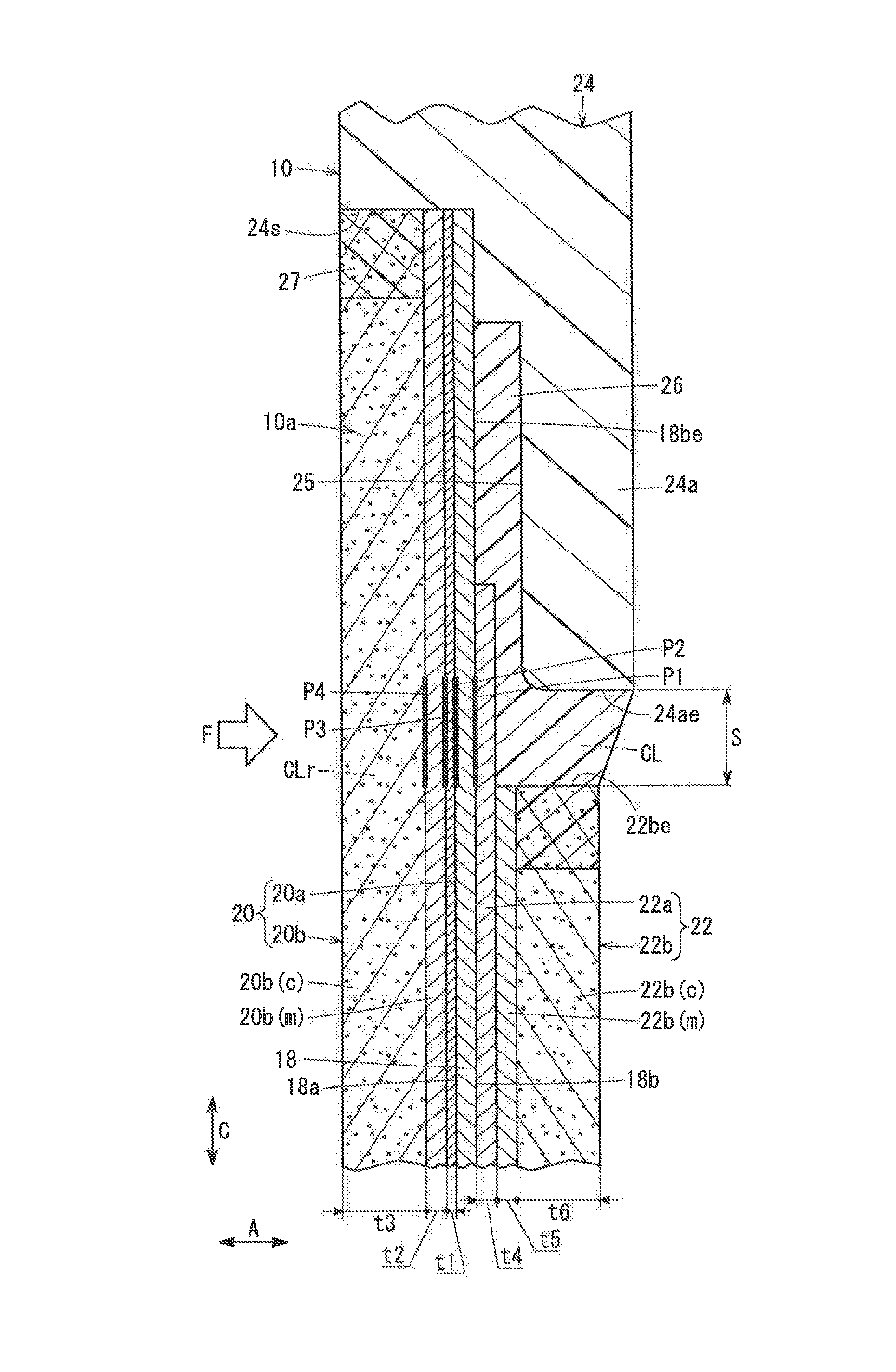
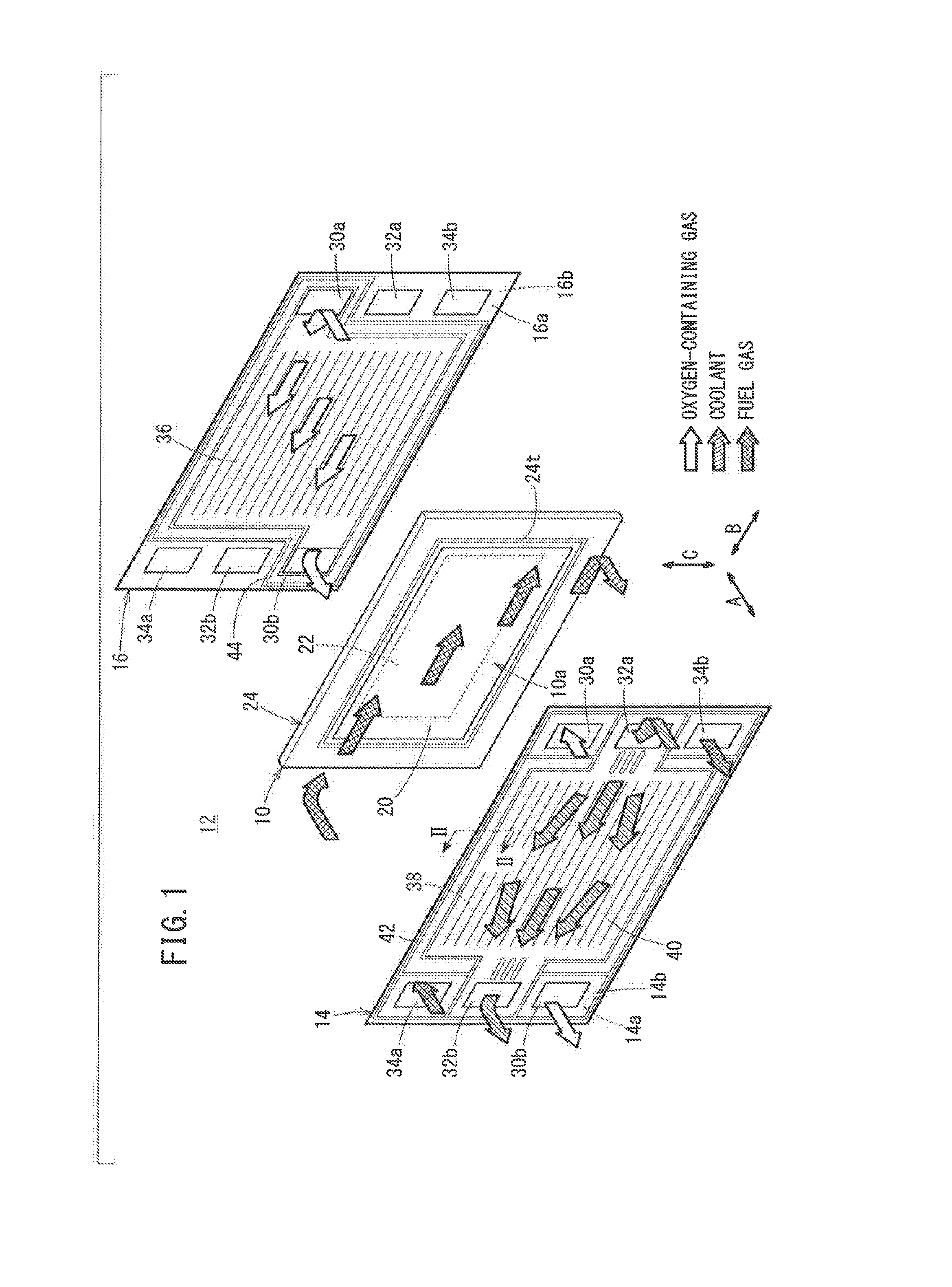
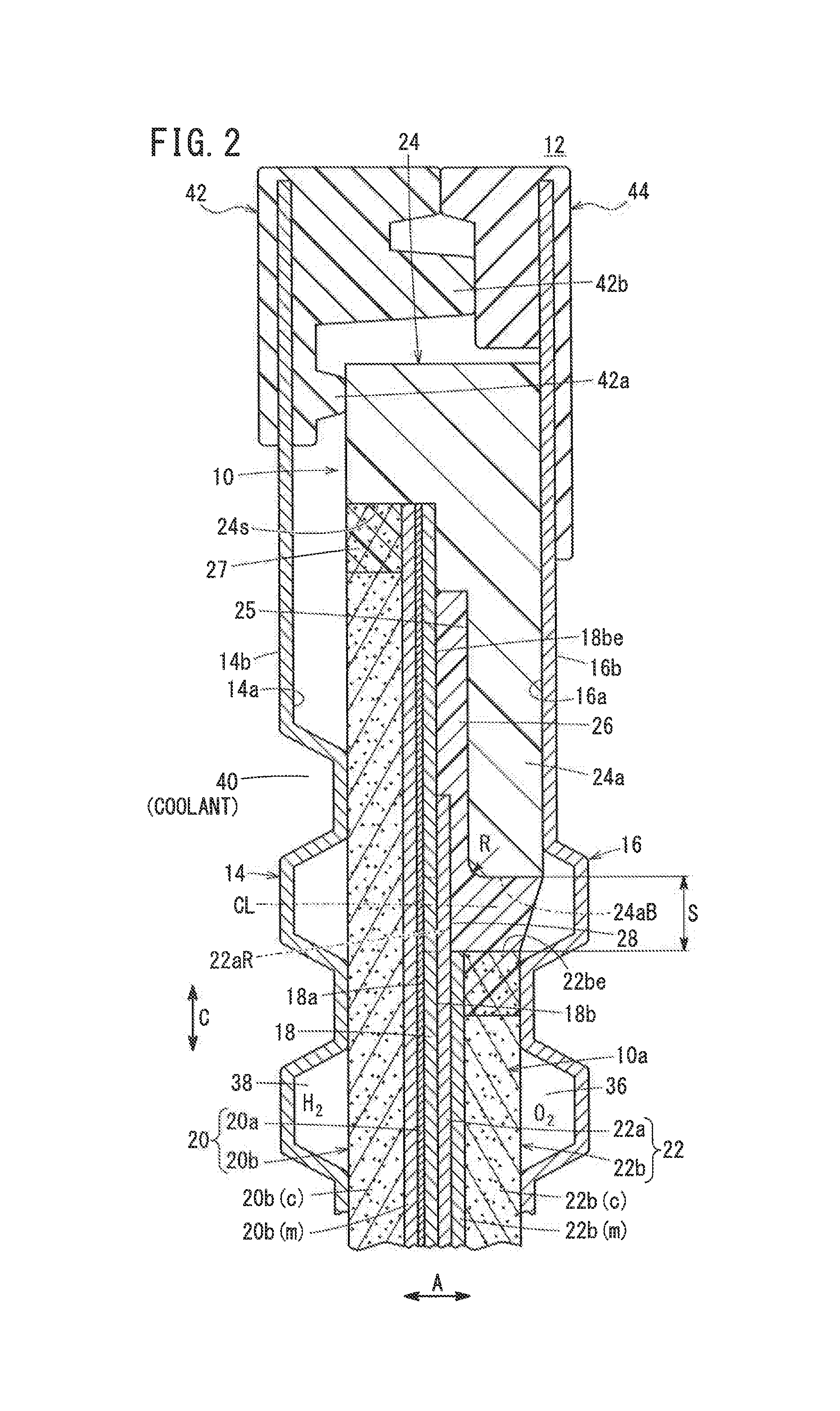
[0038]As shown in FIGS. 1 and 2, a resin frame equipped membrane electrode assembly 10 according to an embodiment of the present invention is included in a laterally elongated (or longitudinally elongated) rectangular solid polymer power generation cell 12. A plurality of the power generation cells 12 are stacked together in a horizontal direction indicated by an arrow A or in a gravity direction indicated by an arrow C to form the fuel cell stack. For example, the fuel cell stack is mounted as an in-vehicle fuel cell stack, in a fuel cell electric automobile (not shown).

[0039]The power generation cell 12 is formed by sandwiching the resin frame equipped membrane electrode assembly 10 between a first separator 14 and a second separator 16. Each of the first separator 14 and the second separator 16 has a laterally elongated (or longitudinally elongated) rectangular shape. For example, the first separator 14 and the second separator 16 are made of metal plates such as steel plates, st...


PUM

PropertyMeasurementUnit
Lengthaaaaaaaaaa
Lengthaaaaaaaaaa
Fracture energyaaaaaaaaaa

Abstract

A resin frame equipped membrane electrode assembly includes an MEA having different sizes of components and a resin frame member. A clearance is formed between an outer end of a second gas diffusion layer and an inner expansion. The second electrode layer has a frame shaped outer marginal portion provided at the clearance. The crack density of cracks of the frame shaped outer marginal portion is 30 cracks / mm2 or less, and the interval between the cracks is 0.06 mm or more.

Description

CROSS-REFERENCE TO RELATED APPLICATIONS[0001]This application is based upon and claims the benefit of priority from Japanese Patent Applications No. 2015-142111 filed on Jul. 16, 2015, No. 2015-149288 filed on Jul. 29, 2015 and No. 2015-149295 filed on Jul. 29, 2015, the contents all of which are incorporated herein by reference.BACKGROUND OF THE INVENTION[0002]Field of the Invention[0003]The present invention relates to a resin frame equipped membrane electrode assembly for a fuel cell. The resin frame equipped membrane electrode assembly includes an MEA having different sizes of components, i.e., an MEA including a solid polymer electrolyte membrane and a first electrode and a second electrode having different surface sizes sandwiching the solid polymer electrolyte membrane. Further, the resin frame equipped membrane electrode assembly includes a resin frame member provided around the MEA.[0004]Description of the Related Art[0005]In general, a solid polymer electrolyte fuel cell e...

Claims


Application Information

Patent Timeline
IPC IPC(8): H01M8/0273H01M8/0284H01M8/1004
CPCH01M8/0273H01M2008/1095H01M8/0284H01M8/1004H01M8/04783H01M8/0276H01M8/242H01M2250/20Y02E60/50Y02T90/40
Inventor OHMORI, SUGURUSUGISHITA, MASASHIKATO, TAKASHITANAKA, YUKIHITOSUGIURA, SEIJI
Owner HONDA MOTOR CO LTD
Learn More