Semi-passive control of solidification in powdered materials

a technology of semi-passive control and powdered materials, applied in the field of powdered materials, can solve the problems of inability to use this prior-art process, limited microstructure control to grain size, and no known method to develop three-dimensional nanoparticle architectures within metal microstructures

Active Publication Date: 2017-01-26
HRL LAB
View PDF2 Cites 43 Cited by
  • Summary
  • Abstract
  • Description
  • Claims
  • Application Information

AI Technical Summary

Benefits of technology

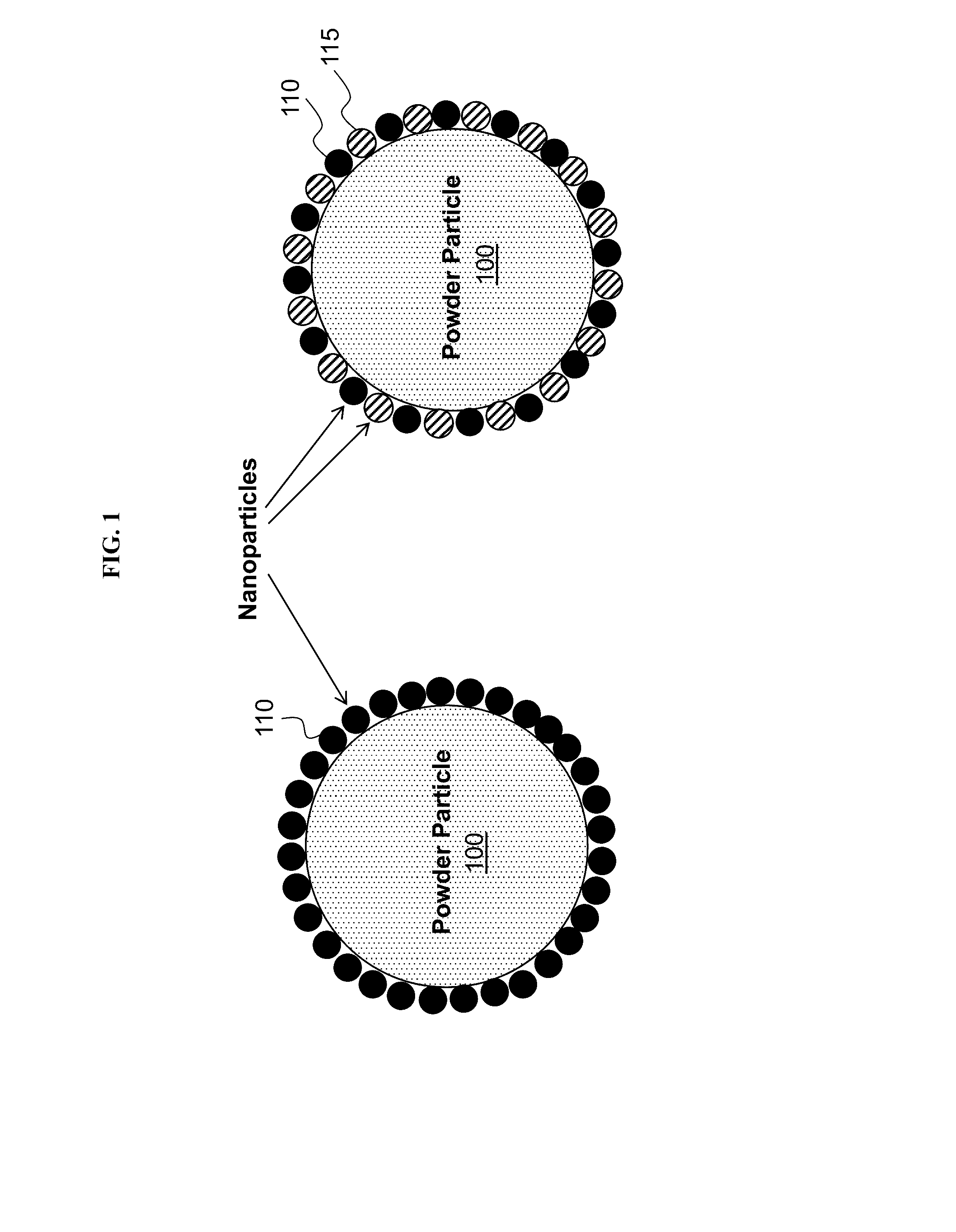
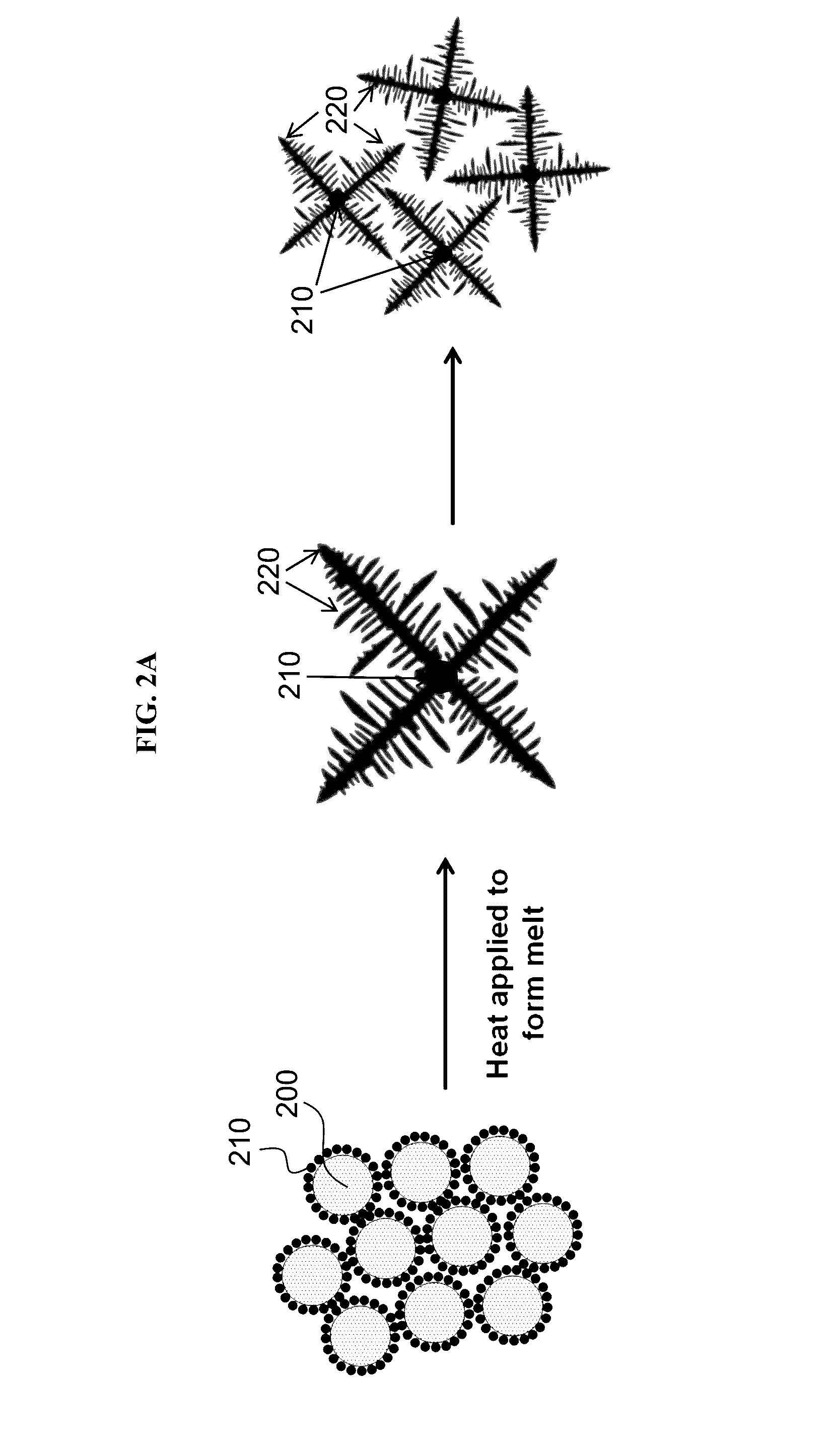
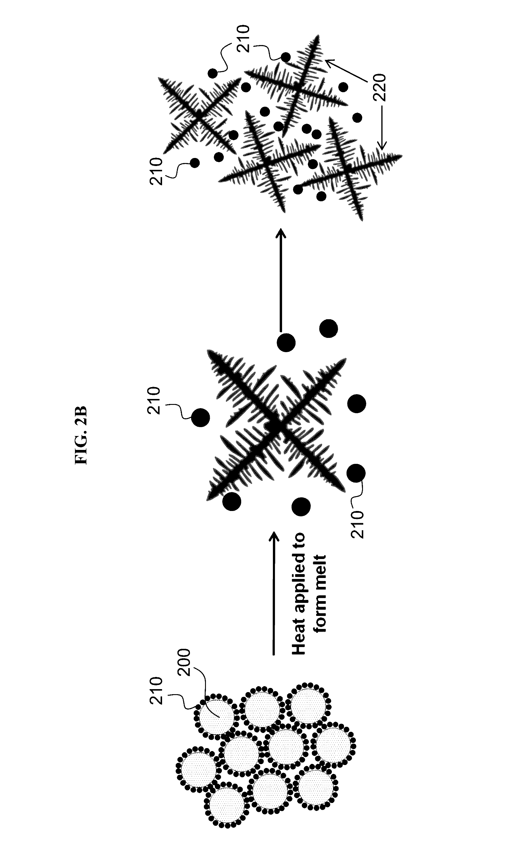
[0021]In some embodiments, the solid state is a layered microstructure containing one or more layers comprising the nanoparticles and / or microparticles.
[0022]The method may further include creating a structure through one or more techniques selected from the group consisting of additive manufacturing, injection molding, pressing and sintering, capacitive discharge sintering, and spark plasma sintering. The present invention provides a solid object or article comprising a structure produced by a process comprising such a method.

Problems solved by technology

This microstructure control is limited to grain size and grain orientation control.
Metal particles and certain desirable ceramic particles would likely be dissolved and therefore cannot be used in this prior-art process.
There are no known methods to develop three-dimensional nanoparticle architectures within metal microstructures.

Method used


Image

  • Semi-passive control of solidification in powdered materials
  • Semi-passive control of solidification in powdered materials
  • Semi-passive control of solidification in powdered materials

Examples


Embodiment Construction

[0042]The compositions, structures, systems, and methods of the present invention will be described in detail by reference to various non-limiting embodiments.

[0043]This description will enable one skilled in the art to make and use the invention, and it describes several embodiments, adaptations, variations, alternatives, and uses of the invention. These and other embodiments, features, and advantages of the present invention will become more apparent to those skilled in the art when taken with reference to the following detailed description of the invention in conjunction with the accompanying drawings.

[0044]As used in this specification and the appended claims, the singular forms “a,”“an,” and “the” include plural referents unless the context clearly indicates otherwise. Unless defined otherwise, all technical and scientific terms used herein have the same meaning as is commonly understood by one of ordinary skill in the art to which this invention belongs.

[0045]Unless otherwise ...


PUM

PropertyMeasurementUnit
particle sizeaaaaaaaaaa
vol %aaaaaaaaaa
wt %aaaaaaaaaa

Abstract

Disclosed herein are surface-functionalized powders which alter the solidification of the melted powders. Some variations provide a powdered material comprising a plurality of particles fabricated from a first material, wherein each of the particles has a particle surface area that is continuously or intermittently surface-functionalized with nanoparticles and/or microparticles selected to control solidification of the powdered material from a liquid state to a solid state. Other variations provide a method of controlling solidification of a powdered material, comprising melting at least a portion of the powdered material to a liquid state, and semi-passively controlling solidification of the powdered material from the liquid state to a solid state. Several techniques for semi-passive control are described in detail. The methods may further include creating a structure through one or more techniques selected from additive manufacturing, injection molding, pressing and sintering, capacitive discharge sintering, or spark plasma sintering.

Description

PRIORITY DATA[0001]This patent application is a non-provisional application with priority to U.S. Provisional Patent App. No. 62 / 192,568, filed Jul. 15, 2015, which is hereby incorporated by reference herein.FIELD OF THE INVENTION[0002]The present invention generally relates to powdered materials, objects containing such powdered materials, and methods of making and using the same.BACKGROUND OF THE INVENTION[0003]Powder processing of metals includes capacitive discharge sintering, direct metal laser melting, electron beam melting, and other techniques. These processes have been used to create near net shape parts, and occasionally to control microstructure. This microstructure control is limited to grain size and grain orientation control. This control is all dependent on heat input. What is desired is to control nucleation and growth kinetics within the structure independent of, or in conjunction with, thermal input.[0004]Prior art exists in which nanoparticles are used in melts to...

Claims


Application Information

Patent Timeline
Patent Type & Authority Applications(United States)
IPC IPC(8): B22F3/10B29C45/00B28B1/00B22F5/00B22F1/00B22F3/16B22F3/105B29C67/00B28B1/24B22F1/054B22F1/17B22F1/18
CPCB22F3/1028B29C67/0077B29C45/0001B28B1/001B28B1/24B22F2003/1051B22F3/16B22F3/105B22F5/00B29K2105/251B22F1/0022B33Y70/00B33Y10/00B22F2998/10B22F2999/00B29C64/153B22F1/054B22F1/17B22F1/18B22F1/056B22F10/34B22F1/16B22F10/28B22F10/20Y02P10/25
Inventor MARTIN, JOHN H.SCHAEDLER, TOBIAS A.YAHATA, BRENNANHUNDLEY, JACOB M.GRAETZ, JASON A.GROSS, ADAM F.CARTER, WILLIAM
Owner HRL LAB
Why Eureka
Try Eureka