Torsion cotter pin and method of use

a cotter pin and bending technology, applied in the direction of pins, fastening means, screws, etc., can solve the problems of not providing the tensile and sheer strength needed in most applications, prone to deformation of free ends of cotter pins, and not aesthetically pleasing, so as to enhance tensile and shear strength, inhibit rust, and reduce the effect of friction

Inactive Publication Date: 2017-01-26
PRIMEAU DANIEL F
View PDF0 Cites 1 Cited by
  • Summary
  • Abstract
  • Description
  • Claims
  • Application Information

AI Technical Summary

Benefits of technology

[0017]It is one objective of the present invention to provide a pin that restrict rotation of the bolt inside the slotted nut.
[0018]It is another objective to provide a pin fabricated from stainless steel, so as to exert greater torsion, enhance tensile and shear strength, and inhibit rust.
[0019]It is another objective to provide a hump on a first free end of the legs to help restrict rotation of the slotted nut relative to the bolt.
[0020]Yet another objective is to provide a generally 90° bend on a second free end of the legs to wedge between the outer threaded surface of the bolt and a threaded inner surface of the slotted nut to further restrict rotation of the slotted nut relative to the bolt.

Problems solved by technology

Thus, the free ends of a cotter pin are generally susceptible to deforming under the stress of torsional forces.
Carbon steel is not as dense an alloy as stainless steel, and thus does not provide tensile and sheer strength needed in most applications.
It is also known that cotter pins are not aesthetically pleasing because the free ends protrude from the hole in the shank which it makes it difficult to cap the nut without interference of the pin.
The problem with these fastening mechanisms is that they do not provide sufficient torsion for retaining the nut in place.
The cotter pins also are not pleasing to view because of the free legs that protrude therefrom.
Also, the carbon steel fabrication has a proclivity to rust and corrode.

Method used


Image

  • Torsion cotter pin and method of use
  • Torsion cotter pin and method of use
  • Torsion cotter pin and method of use

Examples


Embodiment Construction

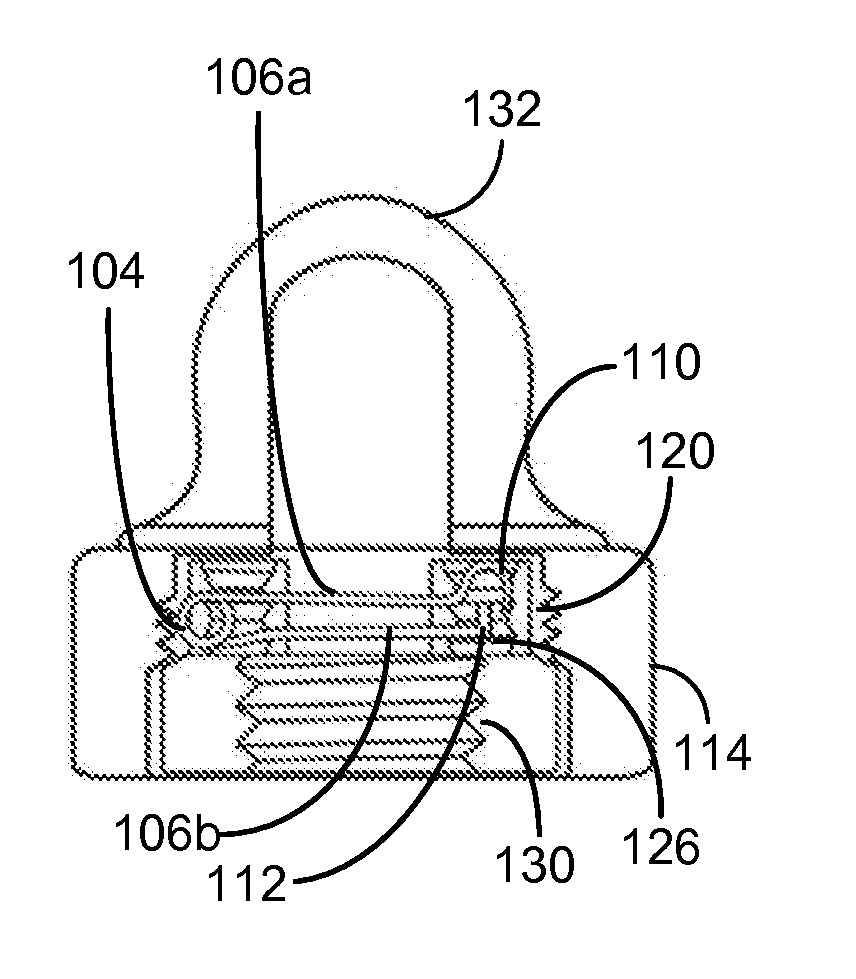
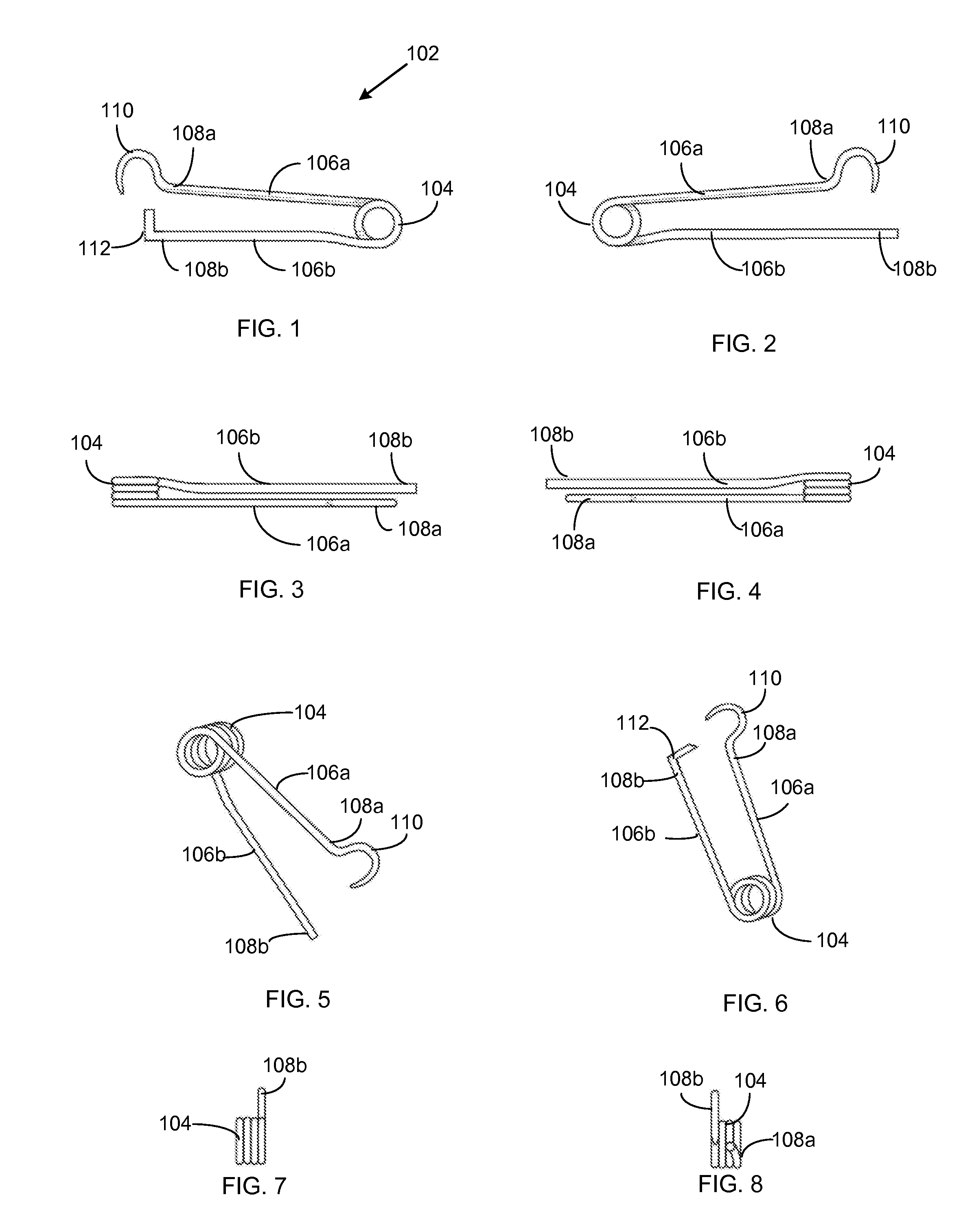
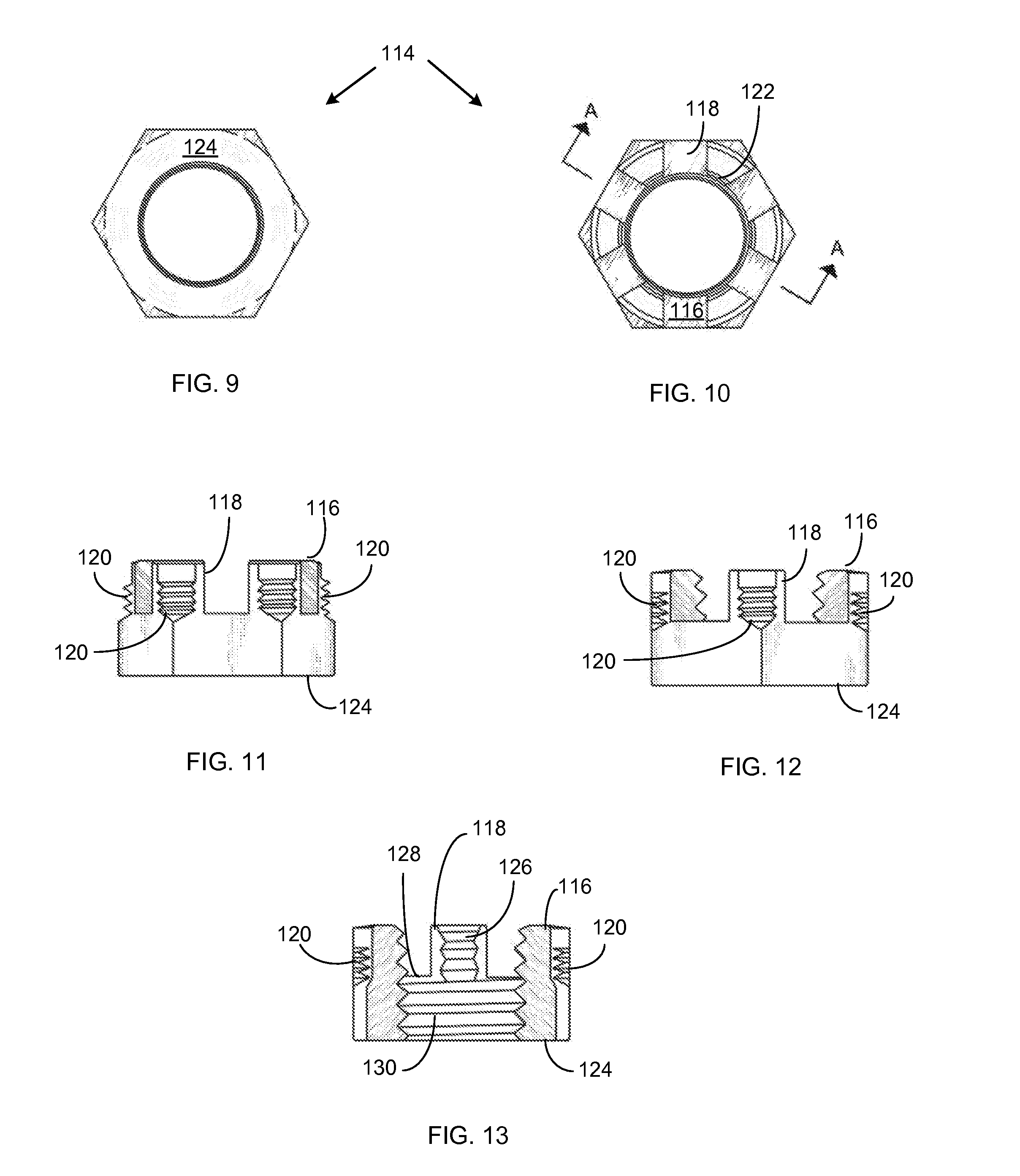
[0050]The following detailed description is merely exemplary in nature and is not intended to limit the described embodiments or the application and uses of the described embodiments. As used herein, the word “exemplary” or “illustrative” means “serving as an example, instance, or illustration.” Any implementation described herein as “exemplary” or “illustrative” is not necessarily to be construed as preferred or advantageous over other implementations. All of the implementations described below are exemplary implementations provided to enable persons skilled in the art to make or use the embodiments of the disclosure and are not intended to limit the scope of the disclosure, which is defined by the claims. For purposes of description herein, the terms “upper,”“lower,”“left,”“rear,”“right,”“front,”“vertical,”“horizontal,” and derivatives thereof shall relate to the invention as oriented in FIG. 1. Furthermore, there is no intention to be bound by any expressed or implied theory pres...


PUM


Abstract

A torsional fastening assembly provides a pin that leverages torque from a torsion spring and a pair of deviated free ends to fix a slotted nut in a locked threaded position. The pin includes a torsion spring that diverges into a pair of legs having free ends. A first free end includes a hump, while a second free end includes a generally 90° bend. The torsion spring exerts a torsional force on the pin that biases the pair of legs to diverge. The legs pass through a slotted nut and a threaded bolt. The hump and the generally 90° bend are engaged around the respective threads of the slotted nut and the bolt, such that the slotted nut is restricted from rotating relative to the bolt. The pin is fabricated from stainless steel to enhance tensile strength and inhibit rust. A cap conceals the pin and the slotted nut.

Description

CROSS REFERENCE OF RELATED APPLICATIONS[0001]This application claims the benefits of U.S. provisional application No. 62 / 029,840, filed Jul. 28, 2014 and entitled TORSION COTTER PIN AND METHOD OF USE, which provisional application is incorporated by reference herein in its entirety.FIELD OF THE INVENTION[0002]The present invention relates generally to a torsional fastening assembly. More so, the present invention relates to a torsional fastening assembly that provides a pin that leverages a torque from a torsion spring and a pair of deviated free ends to fix a slotted nut in a locked threaded position, wherein the pin is disposed within a perimeter of the slotted nut, such that a cap can cover both the pin and the slotted nut, and wherein the pin is fabricated form stainless steel to inhibit rust and corrosion.BACKGROUND OF THE INVENTION[0003]The following background information may present examples of specific aspects of the prior art (e.g., without limitation, approaches, facts, o...

Claims


Application Information

Patent Timeline
Patent Type & Authority Applications(United States)
IPC IPC(8): F16B39/04F16B19/00
CPCF16B19/004F16B39/04
Inventor PRIMEAU, DANIEL F.
Owner PRIMEAU DANIEL F
Why Eureka
Try Eureka