A capacitive sensor and method of use

a capacitive sensor and capacitive technology, applied in the field of capacitive sensors, can solve the problems of large apparatus, inability to miniaturize, portability, and high-volume low-cost manufacturing, and materials are expensive and not readily available on high-volume low-cost standard cmos semiconductor technology, and may interfere with the measurement of analyte,

Active Publication Date: 2017-01-26
ALTRATECH LTD
View PDF10 Cites 26 Cited by
  • Summary
  • Abstract
  • Description
  • Claims
  • Application Information

AI Technical Summary

Benefits of technology

[0007]An object of this invention is to provide a sensor which is more compact and portable, and / or more robust, and / or less expensive to manufacture, and / or which has greater sensitivity to presence of nanometre-scale target components. Another objective is to avoid reference electrodes and expensive noble metals. Another objective is to eliminate corrosion and drift problems of electrodes; and to ensure that the sensor does not degrade or interfere with the analyte material.SUMMARY OF THE INVENTION

Problems solved by technology

The resulting apparatus therefore appears to be large, made of expensive noble and precious metals, and apparently not amenable to miniaturisation, portability, and high-volume low cost manufacturing.
But, these materials are expensive and not readily available on high-volume low-cost standard CMOS semiconductor technologies.
And particles of the reference electrode material may even interfere with the analyte being measured.

Method used


Image

  • A capacitive sensor and method of use
  • A capacitive sensor and method of use
  • A capacitive sensor and method of use

Examples


Embodiment Construction

[0049]The invention will be more clearly understood from the following description of some embodiments thereof, given by way of example only with reference to the accompanying drawings in which:

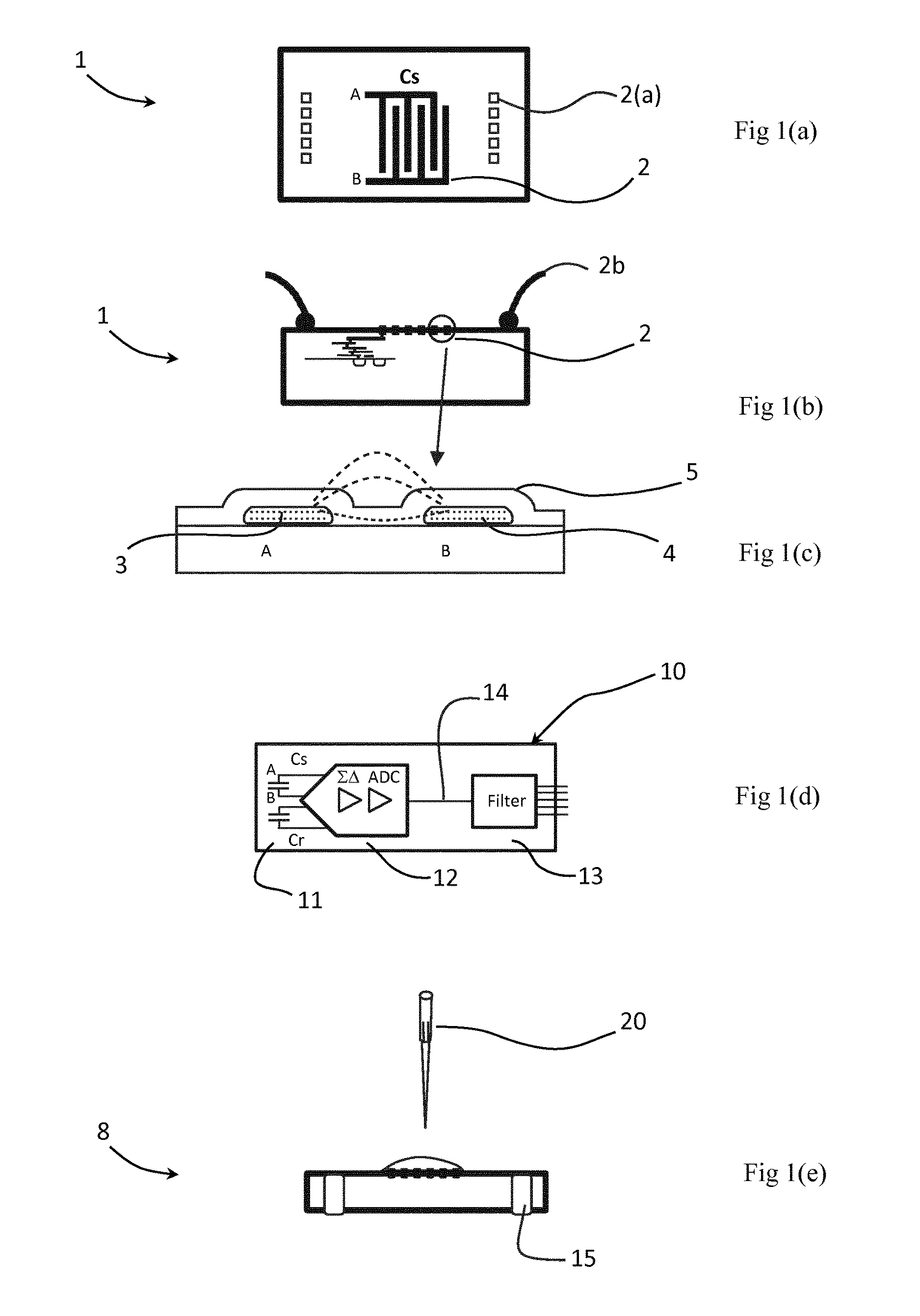
[0050]FIG. 1(a) shows a CMOS semiconductor integrated circuit (IC) sensor of the invention providing inter-digitated capacitive electrodes; FIG. 1(b) shows a cross-section diagram of the CMOS IC; FIG. 1(c) shows a cross-section of two electrodes (A and B) of one of the capacitive sensors; and FIG. 1(d) is an electrical schematic of the sensing capacitor and a reference capacitor forming the differential front-end of a sigma-delta converter;

[0051]FIG. 1(e) shows a cross-section of a TSV version of the CMOS IC, with an analyte droplet dispensed on the sensor;

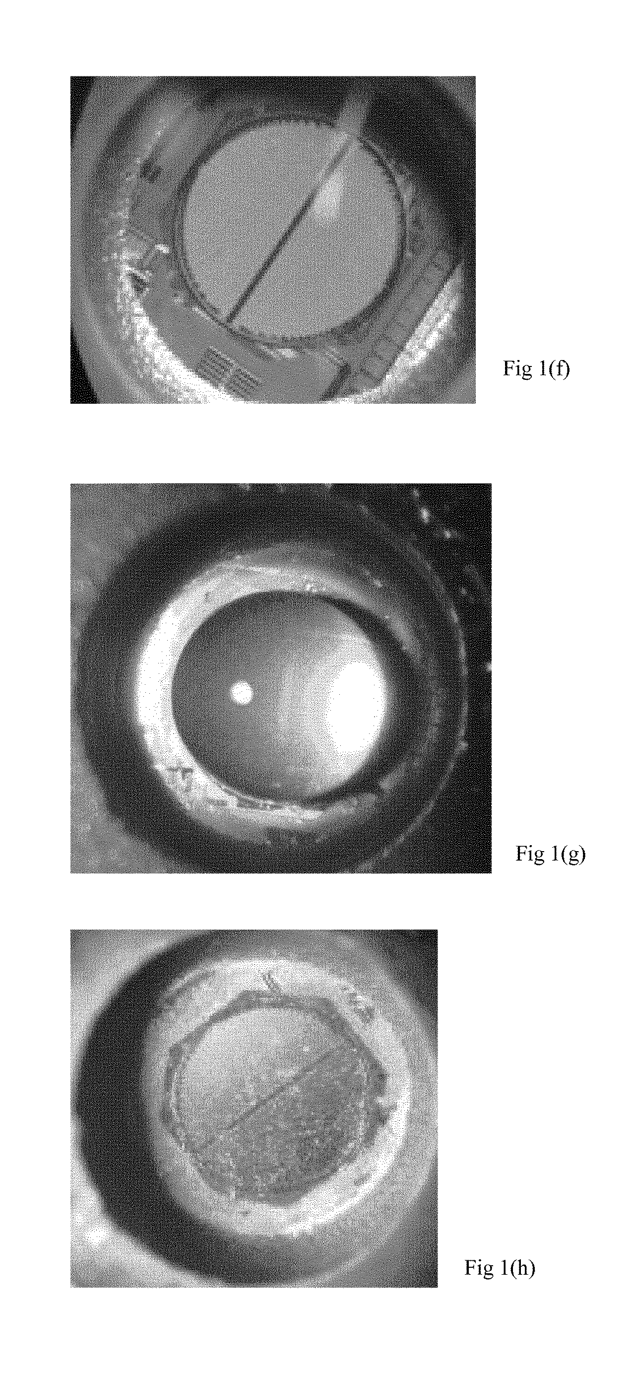
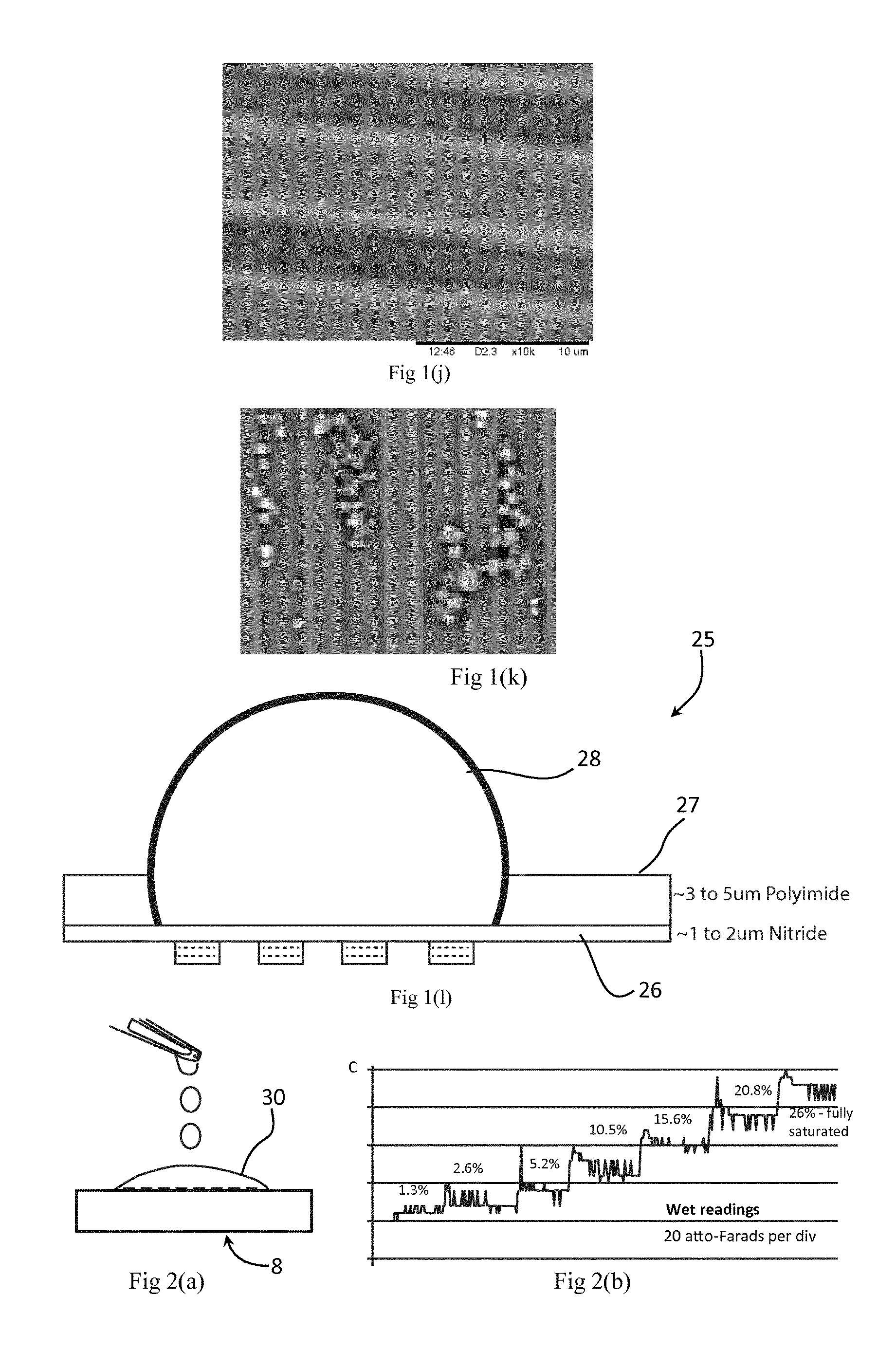
[0052]FIG. 1(f) shows a top-view photo of a circular sensor; FIG. 1(g) shows a 0.4 μl droplet on the sensor; FIG. 1(h) shows the sensor with particles on the sensor after droplet evaporation; and FIG. 1(j) shows a close-up SEM image (approx...


PUM

PropertyMeasurementUnit
thicknessaaaaaaaaaa
diameteraaaaaaaaaa
lengthaaaaaaaaaa

Abstract

An analyte in a liquid sample is detected using a capacitive sensor having electrodes and a sensor surface, and a signal processor. The sample is dried to reduce its liquid content, and capacitive measurements are made after the drying and preferably also before the drying. The sample may include particles, and the analyte is part of or attached to the particles, and the particles provide a major part of the capacitance change compared to absence of particles. In another example the particles are degenerative and form an integral mass upon application of heat, enhancing the extent of capacitance change.

Description

[0001]The invention relates to capacitive sensors arranged to detect and quantify an analyte in a liquid sample over a sensor surface.[0002]Such capacitive sensors are known, being described for example in “Adsorption of Blood Proteins on Metals Using Capacitance Techniques”, by Stoner et al, The Journal of Physical Chemistry, Vol. 74, No. 5, Mar. 5, 1970. This describes two working electrodes upon which blood proteins adsorb, thereby changing the capacitance between the electrodes. A third (reference) electrode is shown immersed in the liquid, to control the DC voltage. While this arrangement appears effective for the target blood proteins, it is notable that the working electrodes are large (0.05 cm2) to obtain sufficient capacitance (microfarads) to be measured externally, and are made of noble metals (gold, platinum, mercury) to reduce corrosion, oxidation, or reaction with the liquid solution. The reference electrode is formed of platinized platinum. The resulting apparatus the...

Claims


Application Information

Patent Timeline
Patent Type & Authority Applications(United States)
IPC IPC(8): G01N27/22G01N33/543C12Q1/68G01R27/26
CPCG01N27/221G01N27/223C12Q1/6825G01N33/5438G01R27/2605G01N27/3276G01N27/745C12Q2563/116C12Q2565/519G01N33/543
Inventor CUMMINS, TIMOTHYO'FARRELL, BRIAN
Owner ALTRATECH LTD
Why Eureka
Try Eureka