Generator comprising a variable speed magnetic gear

a technology of variable speed and generator, which is applied in the direction of electric vehicles, dynamo-electric machines, electrical apparatus, etc., can solve the problems of high speed operation, high cost, and reduced average time to component failure, so as to reduce the number of moving parts, and reduce the effect of cos

a technology of variable speed and generator, which is applied in the direction of electric vehicles, dynamo-electric machines, electrical apparatus, etc., can solve the problems of high speed operation, high cost, and reduced average time to component failure, so as to reduce the number of moving parts, and reduce the effect of cos

US20170025977A1Active Publication Date: 2017-01-26JAGUAR LAND ROVER LTD

Image

  • Generator comprising a variable speed magnetic gear
  • Generator comprising a variable speed magnetic gear
  • Generator comprising a variable speed magnetic gear

Examples


Embodiment Construction

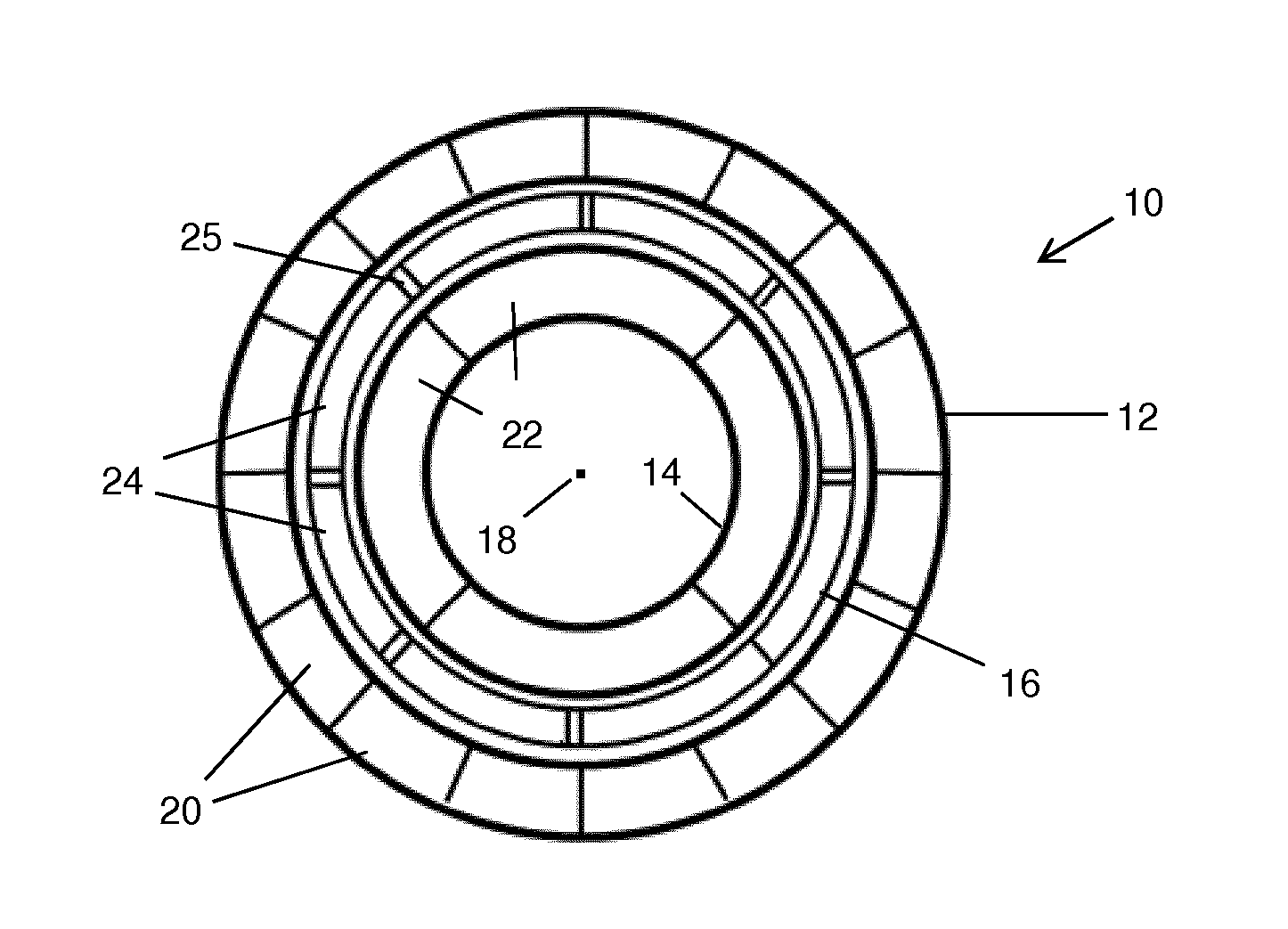
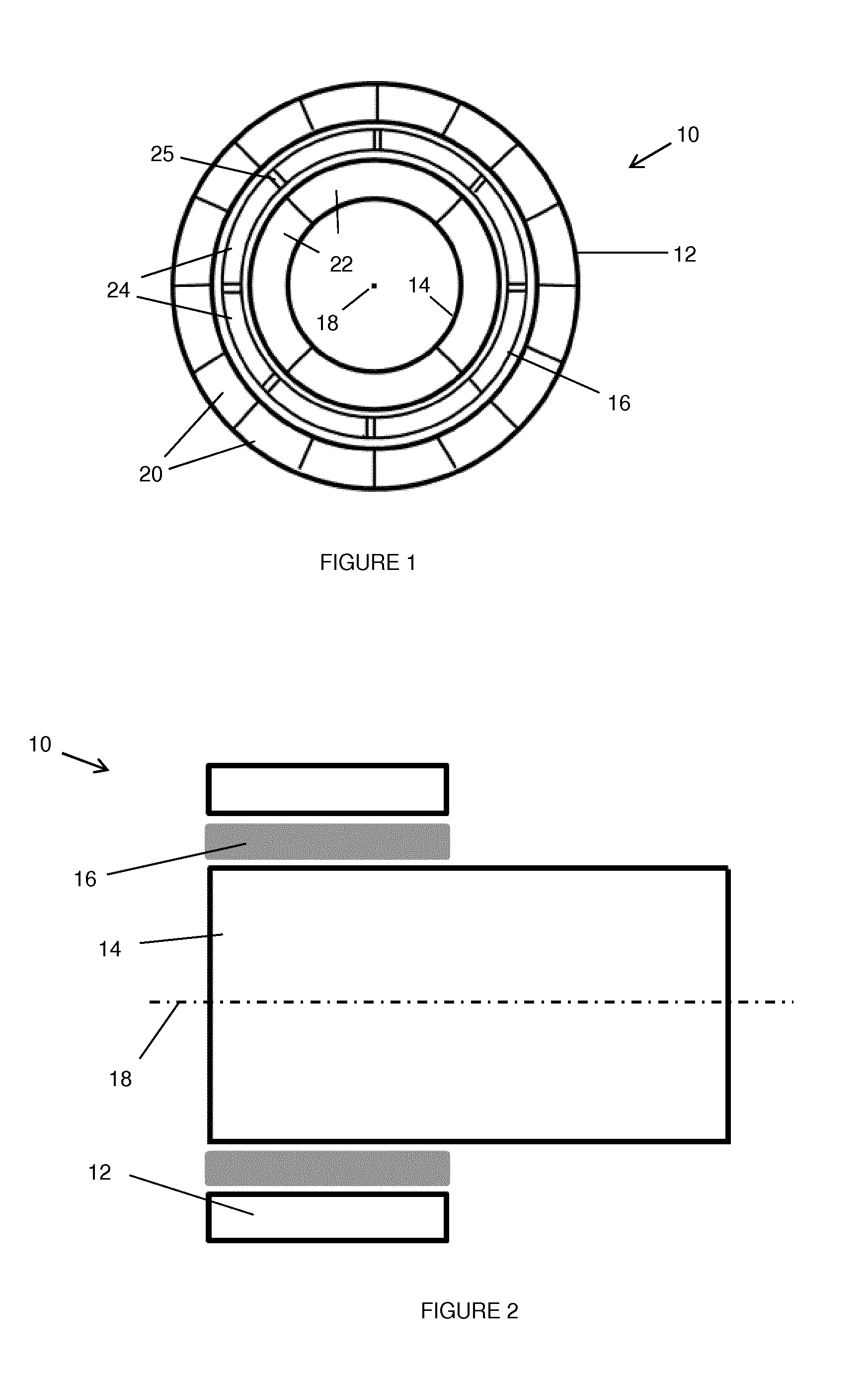
[0090]With reference to FIGS. 1 and 2, a magnetic gear 10 according to an embodiment of the invention is illustrated. The magnetic gear 10 includes three generally tubular members separated by air gaps, and disposed in concentric relation: a stationary outer member, hereafter referred to as a stator 12; an inner rotatable member, hereafter referred to as an inner rotor 14; and an intermediate rotatable member, hereafter referred to as an intermediate rotor 16. The intermediate rotor 16 is disposed between the stator 12 and the inner rotor 14. The inner and intermediate rotors 14, 16 are arranged for independent rotation about a common axis 18.

[0091]As shown most clearly in FIG. 2, in this embodiment the front ends of the stator 12 and the inner and intermediate rotors 14, 16 (shown to the left in FIG. 2) are substantially coplanar. The stator 12 and the intermediate rotor 16 are approximately equal in length along the axis 18, whereas the inner rotor 14 extends beyond both the stato...


PUM


Abstract

A generator comprising a magnetic gear, the magnetic gear comprising a stationary member comprising a set of electromagnets, a first moveable member comprising a set of magnets, and a second moveable member disposed between the first moveable member and the stationary member. The second moveable member comprises a set of core members. The first and second moveable members are magnetically coupled to define a gear ratio therebetween and the electromagnets are operable to control the gear ratio. The stationary member comprises a stator of the generator and the first moveable member comprises an armature of the generator, wherein the armature is arranged to induce an electrical current in a set of generator windings disposed around the stator. The second moveable member comprises an input means arranged to receive a drive force. The gear ratio is variable, such that a variable output speed may be produced for a given input speed. In this way, the electrical output of the generator is decoupled from the input speed, so as to provide sufficient power for a range of input speeds.

Description

FIELD OF THE INVENTION[0001]This disclosure relates to a generator comprising a variable speed magnetic gear. Aspects of the invention relate to a magnetic gear, a magnetic gear system, a generator, a generator system, a vehicle and a method for operating a magnetic gear.BACKGROUND[0002]As a result of recent changes in emissions regulations, there is widespread interest in reducing engine speeds in modern vehicles. In particular, it is desirable to reduce the idling speed of vehicle engines as far as possible, and also the engine speed at which automatic transmission systems select a higher gear, in order to comply with environmental legislation.[0003]At the same time, the demand for electrical power in vehicles has been rising. This is in part due to the fact that modern vehicles typically include a large range of internal systems such as climate control, seat warming, infotainment systems, and so on. Often, the time when the electrical demand is highest coincides with a period of ...

Claims


Application Information

Patent Timeline
26 Jan 2017
Publication
US20170025977A1
IPC
H02P9/06; H02K49/10; B60L1/00; H02K7/18; H02K16/02
CPC
H02P9/06; H02K7/1815; H02K49/102; B60L1/00; H02K16/02; H02K7/006; H02K7/11; H02K16/00
Inventors
ARMSTRONG, ALAN