
Off-state isolation enhancement for feedback amplifiers

a feedback amplifier and off-state isolation technology, which is applied in differential amplifiers, amplifiers with semiconductor devices/discharge tubes, amplifier details, etc., can solve the problems of severe deformation, and negatively affecting the performance of the amplifier when it is operating normally (i.e., on-state), so as to increase off-state isolation and improve the effect of isolation

Inactive Publication Date: 2017-01-26
BAE SYST INFORMATION & ELECTRONICS SYST INTERGRATION INC
View PDF2 Cites 7 Cited by
  • Summary
  • Abstract
  • Description
  • Claims
  • Application Information

AI Technical Summary

Benefits of technology

The present disclosure provides a feedback amplifier with a unique feedback network that includes two cross-coupled switches that isolate the amplifier from extraneous electrical signals when the amplifier is powered off. The cross-coupled switches interconnect two feedback paths to cancel out unwanted signals. The feedback amplifier also provides on-state advantages to selectively engage different amplifier characteristics and parameters. The technical effects of this patent text include improved isolation, reduced parasitic effects, and improved performance of the feedback amplifier.

Problems solved by technology

However, benefits aside, there are some known drawbacks.
In many electrical systems, high isolation is desirable when the amplifier is powered down (off-state), and the feedback paths of a differential feedback amplifier can severely degrade this.
To increase off-state isolation, switches can be added in series, but these negatively impact the performance of the amplifier when it is operating normally.
Some conventional amplifiers utilizes switches along the feedback path or switches near the feedback systems / circuitry to enable selective control of the feedback signal, but again these negatively impact the performance of the amplifier when it is operating normally (i.e., on-state).
Issues continue to exist with conventional feedback amplifiers.

Method used


Image

  • Off-state isolation enhancement for feedback amplifiers
  • Off-state isolation enhancement for feedback amplifiers
  • Off-state isolation enhancement for feedback amplifiers

Examples


Embodiment Construction

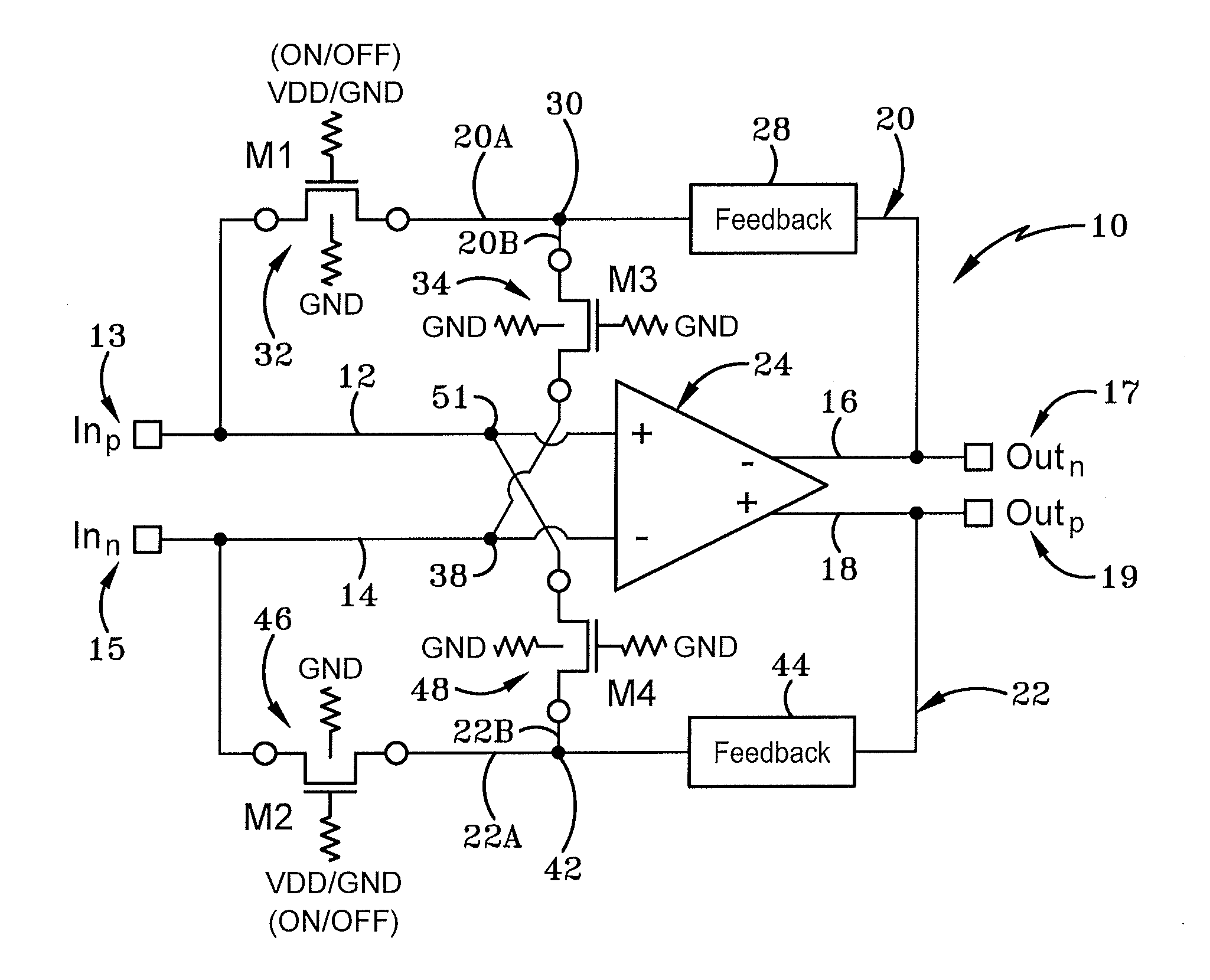
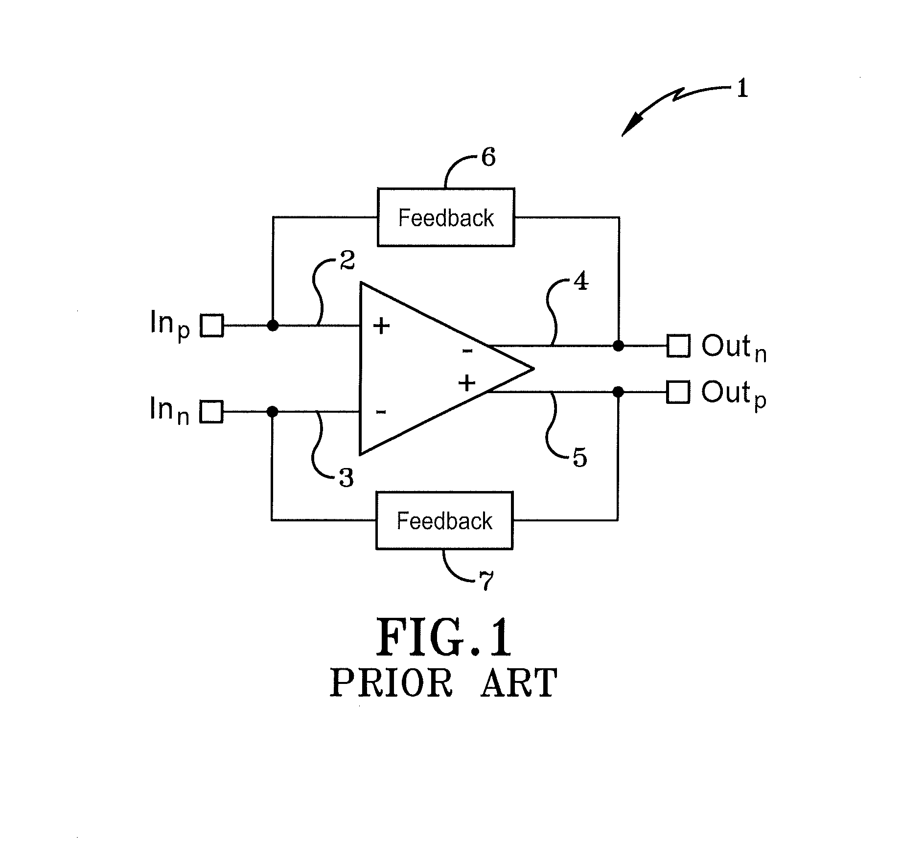
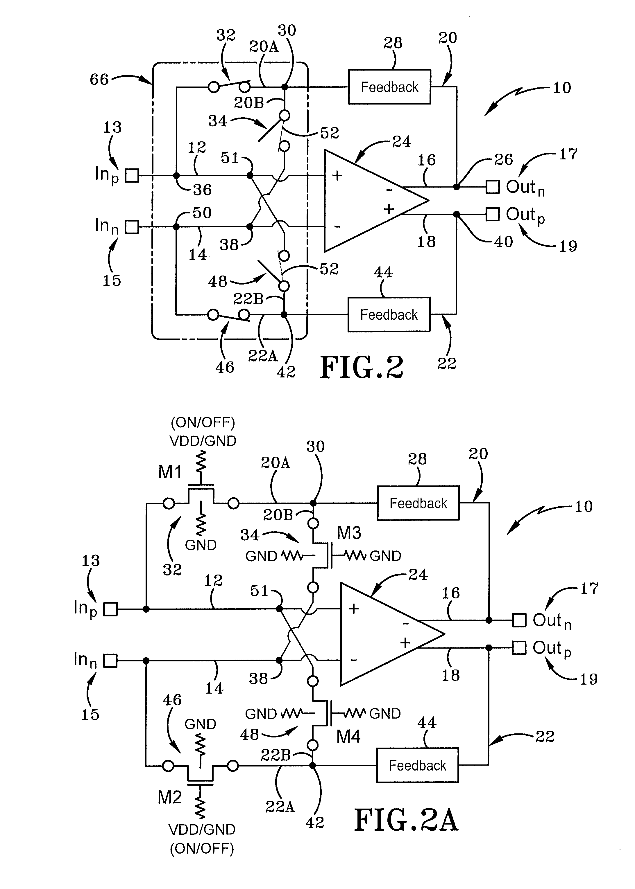
[0030]In general, a differential amplifier amplifies the difference between two input voltages. Differential feedback amplifiers include a feedback path that subtracts a fraction of its output from the input, so that negative feedback opposes the original signal. FIG. 1 depicts a conventional differential amplifier having multiple feedback paths. A conventional differential amplifier 1 is shown and includes positive first voltage input 2, a negative second voltage input 3, a negative first voltage output 4, and a positive second voltage output 5. A first feedback path 6 is connected to and enables feedback to flow from negative first voltage output 4 back to positive first voltage input 2. A second feedback path 7 is connected to and enables feedback to flow from positive second voltage output 5 back to negative second voltage input 3. Stated otherwise, in the differential amplifier 1, each respective feedback path starting point at the voltage output is associated with an opposite ...


PUM


Abstract

A feedback amplifier having an improved feedback network including two cross coupled switches that isolate the amplifier from extraneous undesired electrical signals present in a system or network when the amplifier is turned off (i.e., in an off-state). The cross coupled switches interconnect two feedback paths of a feedback network to enable out-of-phase differential signals to be summed and effectively canceled. Further, the feedback amplifier provides on-stage advantages to enable different amplifier characteristics and parameter to be selectively engaged by turning on or turning off certain feedback networks.

Description

CROSS REFERENCE TO RELATED APPLICATIONS[0001]This application claims the benefit of prior U.S. Provisional Application Ser. No. 62 / 196,638, filed on Jul. 24, 2015; the disclosure of which is incorporated herein by reference.STATEMENT OF GOVERNMENT INTEREST[0002]This invention was made with United States Government support under Contract No. HR0011-12-C-0083 awarded by DARPA. The United States Government has certain rights in this inventionBACKGROUND[0003]Technical Field[0004]The present disclosure relates generally to differential feedback amplifiers. More particularly, the present disclosure relates to differential feedback amplifiers having multiple feedback paths. Specifically, the present disclosure relates to feedback paths incorporating cross-coupled switches for differential feedback amplifiers.[0005]Background Information[0006]Data transmission often requires the use of an amplifier to amplify a signal. One exemplary data transmission utilizes differential signaling. Differe...

Claims


Application Information

Patent Timeline
IPC IPC(8): H03F1/30H03F3/45H03F1/34
CPCH03F1/305H03F1/342H03F2200/153H03F2203/45141H03F3/45179H03F1/3211H03F3/45475H03F3/45977H03F3/72H03F2203/45534H03F2203/45562
Inventor STUENKEL, MARK E.SLIECH, KEVIN W.
Owner BAE SYST INFORMATION & ELECTRONICS SYST INTERGRATION INC
Learn More