Suppressor and flash hider device for firearms having dual path gas exhaust

a suppressor and concealed device technology, applied in the direction of muzzle attachments, weapons, weapon components, etc., can solve the problems of suppressor instability, difficult or impossible to remove clean and reassemble the components of the suppressor device, and continue to foul the baffles, chambers and threads, etc., to enhance the flow of propellant gas and dissipate

Inactive Publication Date: 2017-02-02
LARUE MARK C
View PDF18 Cites 16 Cited by
  • Summary
  • Abstract
  • Description
  • Claims
  • Application Information

AI Technical Summary

Benefits of technology

[0009]It is a principal feature of the present invention to provide a novel noise and flash suppressor mechanism for firearms that provides dual flow paths for propellant gas propagation through a suppressor

Problems solved by technology

When a suppressor device is releasably attached to a firearm barrel, repeated firing of the firearm typically causes continuous fouling of the baffles, chambers and threads of the suppressor by accumulation of cartridge powder residue.
Thus, when the threads of the suppressor or the threads of a firearm barrel become fouled it may be difficult or impossible to remove clean and reassemble the components of a suppressor device.
This undesirable characteristic is common to most types of suppressors and represents a distinct disadvantage when working with the firearm during field con

Method used


Image

  • Suppressor and flash hider device for firearms having dual path gas exhaust
  • Suppressor and flash hider device for firearms having dual path gas exhaust
  • Suppressor and flash hider device for firearms having dual path gas exhaust

Examples


Embodiment Construction

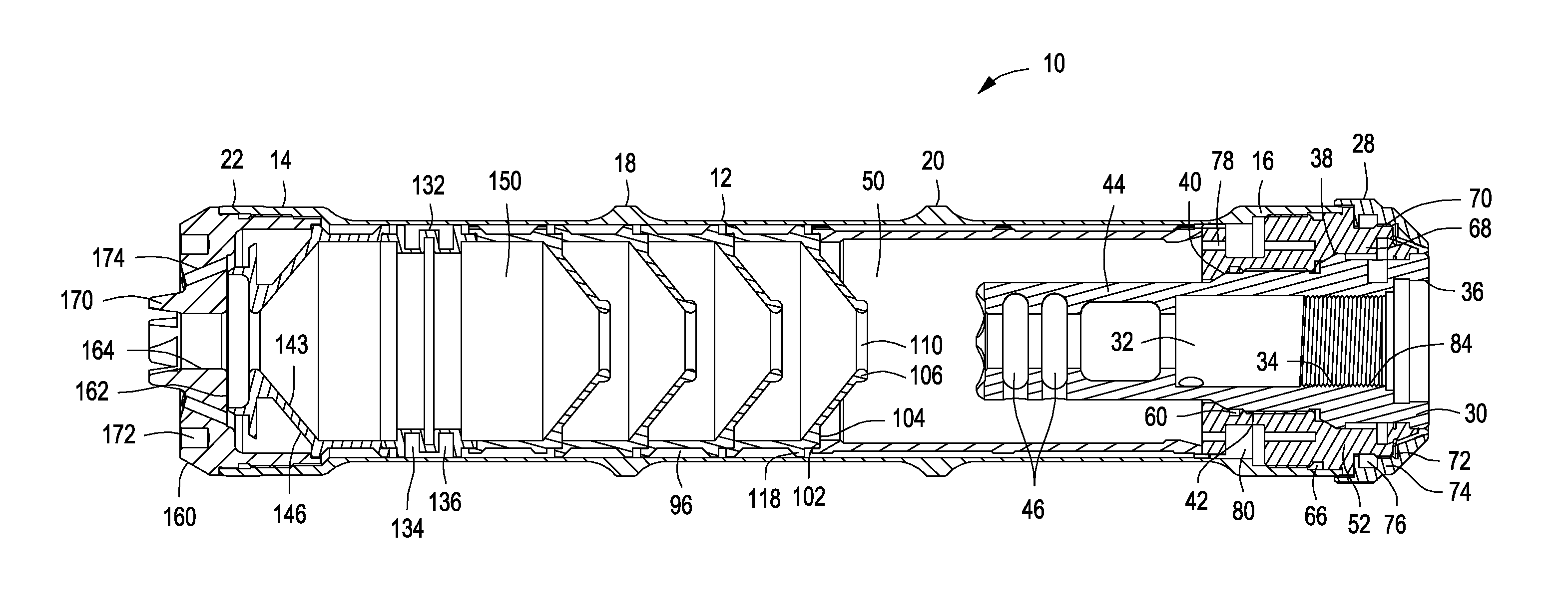
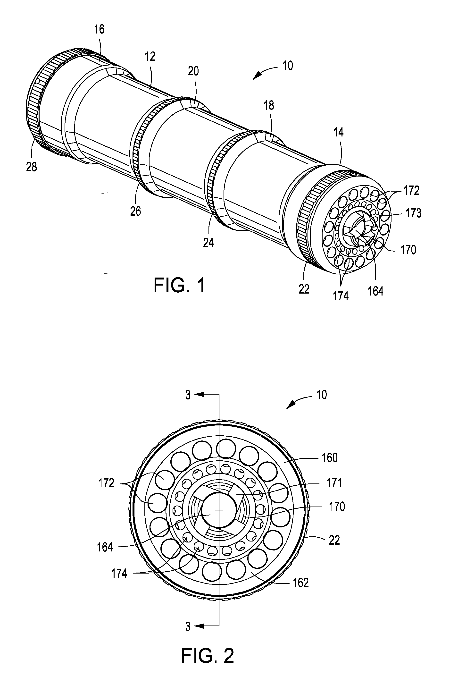
[0026]Referring now to the drawings and first to FIG. 1, a noise suppressor and flash hider device embodying the principles of the present invention is shown generally at 10 and incorporates an elongate tubular housing 12 having a defined length. The tubular housing 12 is strengthened at its forward and rear ends by generally cylindrical thickened enlarged housing wall sections 14 and 16 and is strengthened intermediate its extremities by annular external bosses 18 and 20. Circular knurled regions 22, 24 and 26 are defined by the forward enlarged housing wall section and by the intermediate annular bosses 18 and 20. Another circular knurled section 28 is provided at the rear end portion of the suppressor and flash hider assembly 10, the knurled sections being provided to facilitate secure manual grasping of the suppressor device when attaching it to and removing it from the barrel of a firearm,

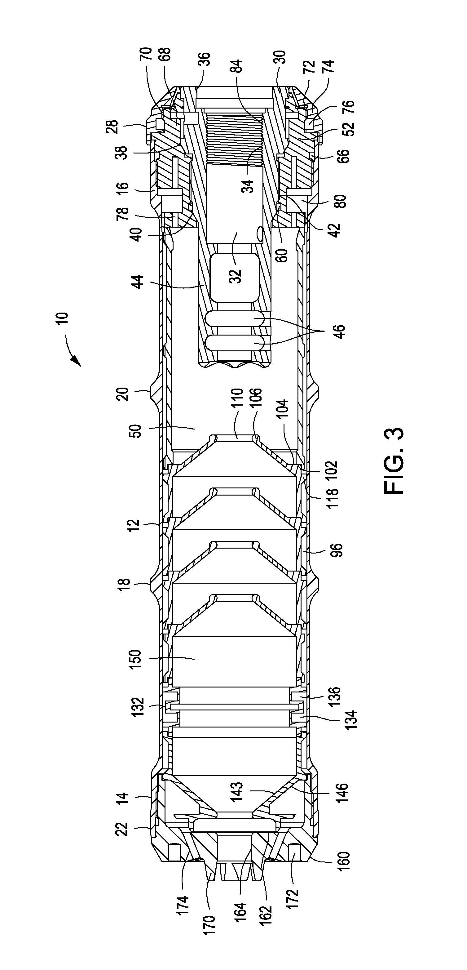
[0027]As shown in FIG. 3 and in greater detail in FIG. 4, a suppressor mounting structure ...


PUM


Abstract

A suppressor and flash hider device for firearms defines primary and secondary propellant gas paths that function simultaneously to quickly decrease gas pressure within the tubular housing of the suppressor to minimize blow-back toward the firearm user. The tubular housing has a collet-like firearm clamping system that establishes symmetrical clamping that will not tend to force the suppressor off coaxial alignment with the firearm barrel to which is mounted. A front wall mounted to the housing defines a central projectile port through which propellant gas also passes and defines an array of angularly oriented discharge passages for discharging propellant gases from the secondary propellant gas path forwardly and angularly toward gas being discharged from the projectile port of the front wall.

Description

BACKGROUND OF THE INVENTION[0001]Field of the Invention[0002]The present invention relates generally to noise and flash suppressors for firearms, particularly rifles, and more particularly concerns suppressors that are specifically designed to minimize the presence of residual propellant gas within a suppressor and rifle bore when the auto-loading mechanism of an auto-loading rifle initiates extraction of a spent cartridge case from the cartridge chamber of the rifle barrel. Even more specifically, this invention concerns minimization of the potential for residual propellant gas blow-back toward a firearm user by enhancing the volume of controlled discharge of propellant gas from noise and flash suppressors so that little if any residual propellant gas pressure is present within a firearm barrel at the time of cartridge case extraction by the auto-loading mechanism of a propellant gas energized firearm.[0003]Description of the Prior Art[0004]A significant number of firearm noise sup...

Claims


Application Information

Patent Timeline
IPC IPC(8): F41A21/30F41A21/32F41A21/34
CPCF41A21/30F41A21/325F41A21/34
Inventor LARUE, MARK C.
Owner LARUE MARK C
Why Eureka
Try Eureka