Device for Subdividing Magnetic Field and Simultaneous Detection of Magnetic Resonance Signals from Multiple Sample Compartments

a magnetic field and magnetic resonance technology, applied in the field of nuclear magnetic resonance (nmr) spectroscopy, can solve the problem of one sample being analyzed

Inactive Publication Date: 2017-02-02
UNIVERSITY OF MISSOURI
View PDF7 Cites 3 Cited by
  • Summary
  • Abstract
  • Description
  • Claims
  • Application Information

AI Technical Summary

Benefits of technology

[0005]A high-level overview of various aspects of the invention is provided here for that reason, to provide an overview of the disclosure and to introduce a selection of concepts that are further described below in the detailed description section below. This summary is not intended to identify key features or essential features of the claimed subject matter, nor is it intended to be used as an aid in isolation to determine the scope of the claimed subject matter.
[0006]Embodiments described herein provide for a device for subdividing magnetic field and simultaneous detection of magnetic resonance signals from multiple sample compartments. The inventive device employs a combination of direct currents and/or radio frequency alternating currents to subdivide a transverse static magnetic field, typically provided by a commercial benchtop NMR spectrometer (or other conventional NMR spectrometer), into multiple volumes that can each test an individual sample. The inventive device deployed with a benchtop NMR (or other conventional NMR) comprises i) at least one electrically conducting member (the “conductor”), ii) at least one power current source for the conductor, and iii) a sample holder compartmentalize

Problems solved by technology

A limitation of benchtop NMR instrumentation is that only one sample can be analyze

Method used


Image

  • Device for Subdividing Magnetic Field and Simultaneous Detection of Magnetic Resonance Signals from Multiple Sample Compartments
  • Device for Subdividing Magnetic Field and Simultaneous Detection of Magnetic Resonance Signals from Multiple Sample Compartments
  • Device for Subdividing Magnetic Field and Simultaneous Detection of Magnetic Resonance Signals from Multiple Sample Compartments

Examples


example 1

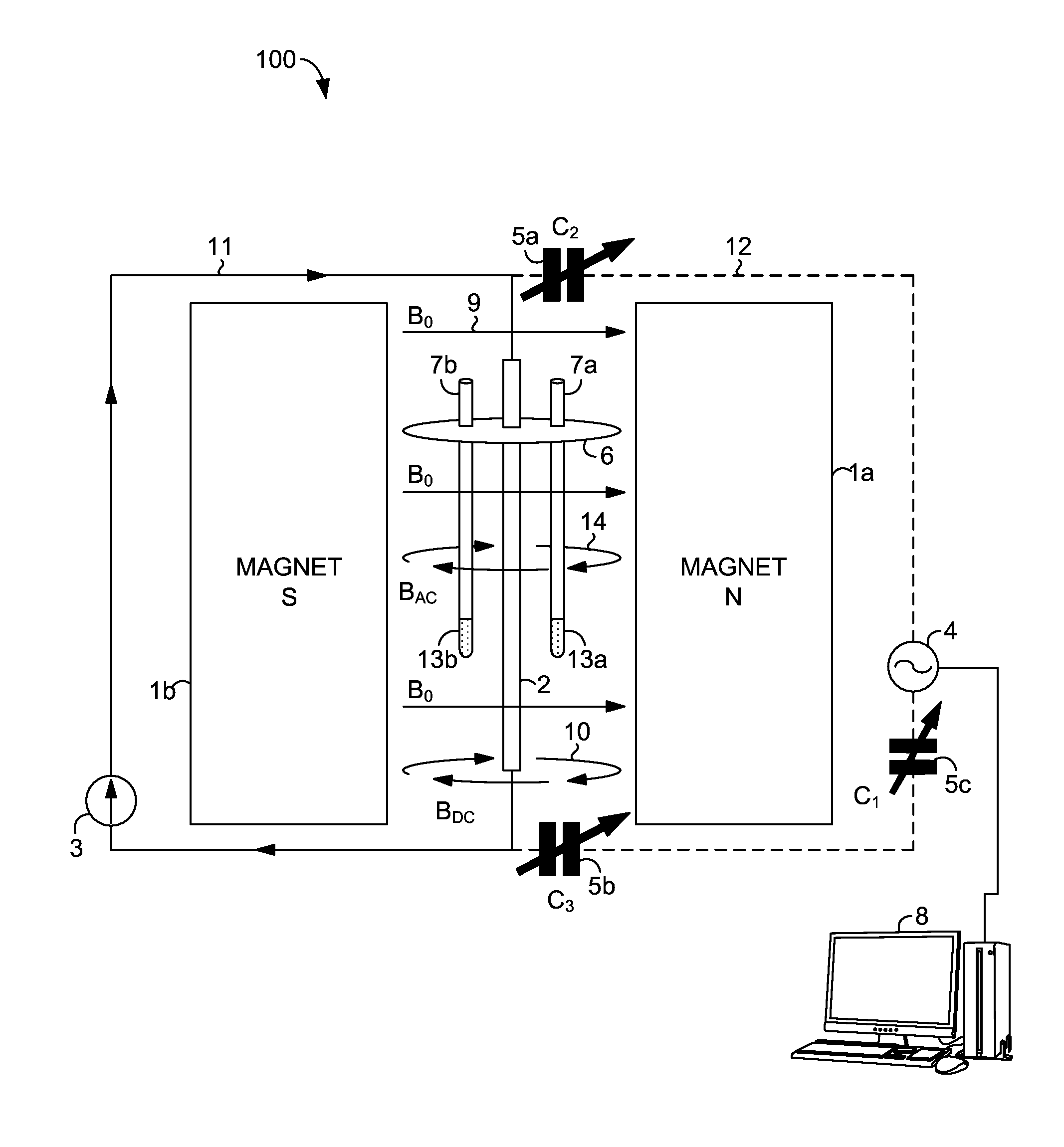
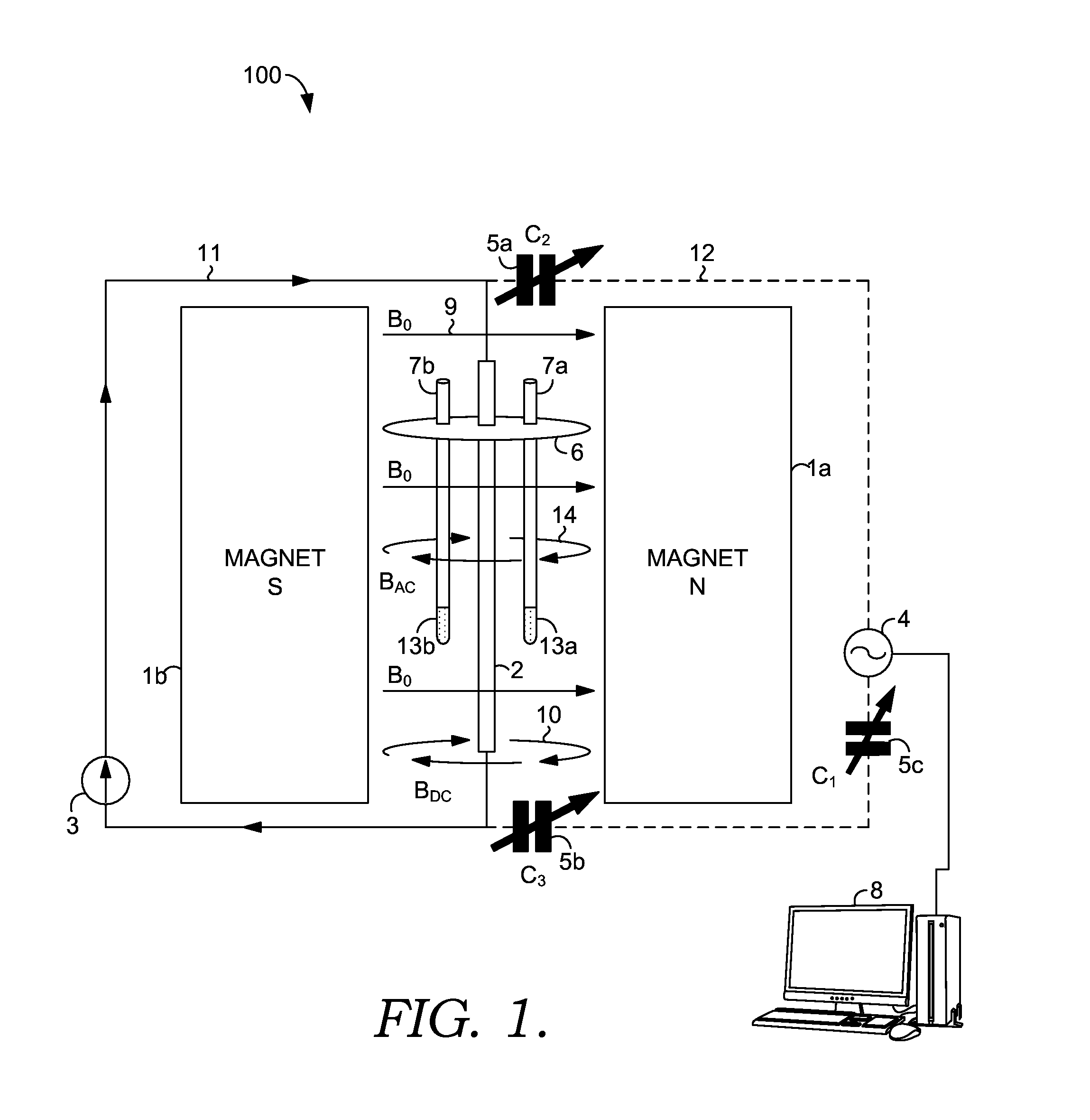
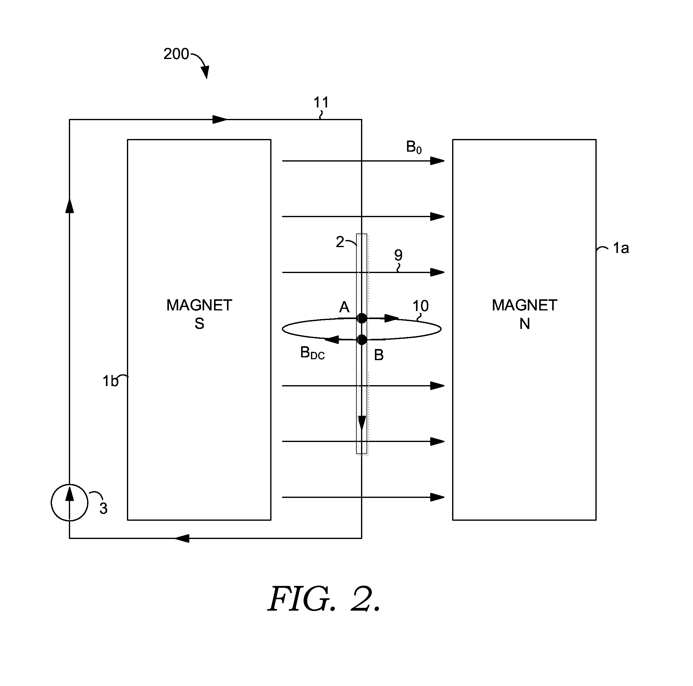
[0048]A procedure for assembling one embodiment of the inventive device includes co-locating a 20-gauge bare copper wire 30 cm in length (the conductor) approximately along the vertical center of a Magritek Spinsolve benchtop NMR spectrometer magnet. The top end of the conductor is connected to the positive terminal and the bottom end to the negative terminal of an adjustable direct current (DC) power supply that can supply 0-10 volts and 0-5 amps. The DC power supply should be set to current limiting mode and adjusted to supply approximately 0.1 volt and 2.0 amps of highly-regulated and stable current.

[0049]A sample holder device is fabricated as a flat thin plastic disk that has a central hole to allow passage of the 20-gauge bare copper wire conductor, and two holes 180 degrees apart, separated along the diameter of the disk by 4.0 mm, located on the disk perimeter and capable of holding two 1 mm glass capillary NMR tubes. Two 20-cm long, 1.0-mm diameter capillary tubes filled wi...

example 2

[0051]A procedure for assembling another embodiment of the inventive device includes positioning a 20-gauge bare copper wire 30 cm in length (the conductor) approximately along the vertical center-axis of a Magritek Spinsolve benchtop NMR spectrometer magnet. The top end of the conductor is connected to the positive terminal and the bottom end to the negative terminal of an adjustable direct current (DC) power supply that can supply 0-10 volts and 0-5 amps. The DC power supply should be set to current limiting mode and adjusted to supply approximately 0.1 volt and 2.0 amps of highly-regulated and stable current.

[0052]A sample holder device is fabricated as a flat thin plastic disk that has a central hole to allow free passage of the 20-gauge bare copper wire conductor, and four holes 90 degrees apart, separated along the diameter of the disk by 4.0 mm, located on the disk perimeter and capable of holding four 1.0 mm glass capillary NMR tubes. Four 20-cm long, 1.0-mm diameter capilla...

example 3

[0054]A procedure for assembling yet another embodiment of the inventive device includes co-locating a 20-gauge bare copper wire 30 cm in length (the conductor) approximately along the vertical center of a Magritek Spinsolve benchtop NMR spectrometer magnet. The top end of the conductor is connected to the positive terminal and the bottom end to the negative terminal of an adjustable direct current (DC) power supply that can supply 0-10 volts and 0-5 amps. The DC power supply should be set to current limiting mode and adjusted to supply approximately 0.1 volt and 2.0 amps of highly-regulated and stable current. The top end of the conductor is also connected to one terminal of a variable matching capacitor and the bottom end to one terminal of a second matching capacitor. The second terminal of the first variable matching capacitor is connected to a radiofrequency (RF) power amplifier. The second terminal of the second variable matching capacitor is connected to one terminal of a var...


PUM


Abstract

Devices and methods are provided for simultaneously interrogating multiple samples using NMR spectroscopy. A first magnetic field is induced. A flow of electricity is induced through a conductive material. The flow of electricity has a direction that is perpendicular to the first magnetic field, and the flow of electricity induces a second magnetic field. A first sample is placed in an additive magnetic field region, where a direction of the first magnetic field and a direction of the second magnetic field are aligned within the additive magnetic field region. A second sample is placed in a canceling magnetic field region, where the direction of the first magnetic field and the direction of the second magnetic field are opposed within the canceling magnetic field region. A free induction decay (FID) of at least the first and second samples is induced.

Description

CROSS-REFERENCE TO RELATED APPLICATION[0001]This application claims the benefit of U.S. Provisional Patent Application No. 62,199,112, filed Jul. 30, 2015, entitled “Device for Subdividing Magnetic Field and Simultaneous Detection of Magnetic Resonance Signals from Multiple Sample Compartments.”GRANT STATEMENT[0002]None.FIELD OF THE INVENTION[0003]The present invention relates to the field of nuclear magnetic resonance (NMR) spectroscopy, more specifically, to a device / method for subdividing magnetic field and simultaneous detection of magnetic resonance signals from multiple sample compartments.BACKGROUND OF THE INVENTION[0004]Chemical, compositional, and homogeneity analyses by benchtop NMR spectroscopy is an emerging field, which substantially reduces the time and cost of sample analyses for the chemical and food industries. Benchtop NMR spectroscopy and imaging are methods of analyses that are particularly suitable for on-line monitoring of processes that involve chemical reacti...

Claims


Application Information

Patent Timeline
IPC IPC(8): G01R33/46G01R33/30G01N24/08
CPCG01R33/4625G01R33/30G01N24/08G01R33/307
Inventor GERALD, II, REX E.
Owner UNIVERSITY OF MISSOURI
Why Eureka
Try Eureka