Transformer and plate coil molded body

a technology of transformer and coil, which is applied in the field of transformer, can solve the problems of complex process for manufacturing transformer, inconvenient coil winding position, and inability to control the coil winding position, etc., and achieve the effect of improving assembly and productivity

Active Publication Date: 2017-02-02
SOLUM CO LTD
View PDF10 Cites 19 Cited by
  • Summary
  • Abstract
  • Description
  • Claims
  • Application Information

AI Technical Summary

Benefits of technology

[0007]Exemplary embodiments of the present disclosure overcome the above disadvantages and other disadvantages not des

Problems solved by technology

However, since a primary coil and a secondary coil provided in the transformer should be insulated from each other in order to secure a space for an insulation distance that is required between the coils and to satisfy t

Method used


Image

  • Transformer and plate coil molded body
  • Transformer and plate coil molded body
  • Transformer and plate coil molded body

Examples


first embodiment

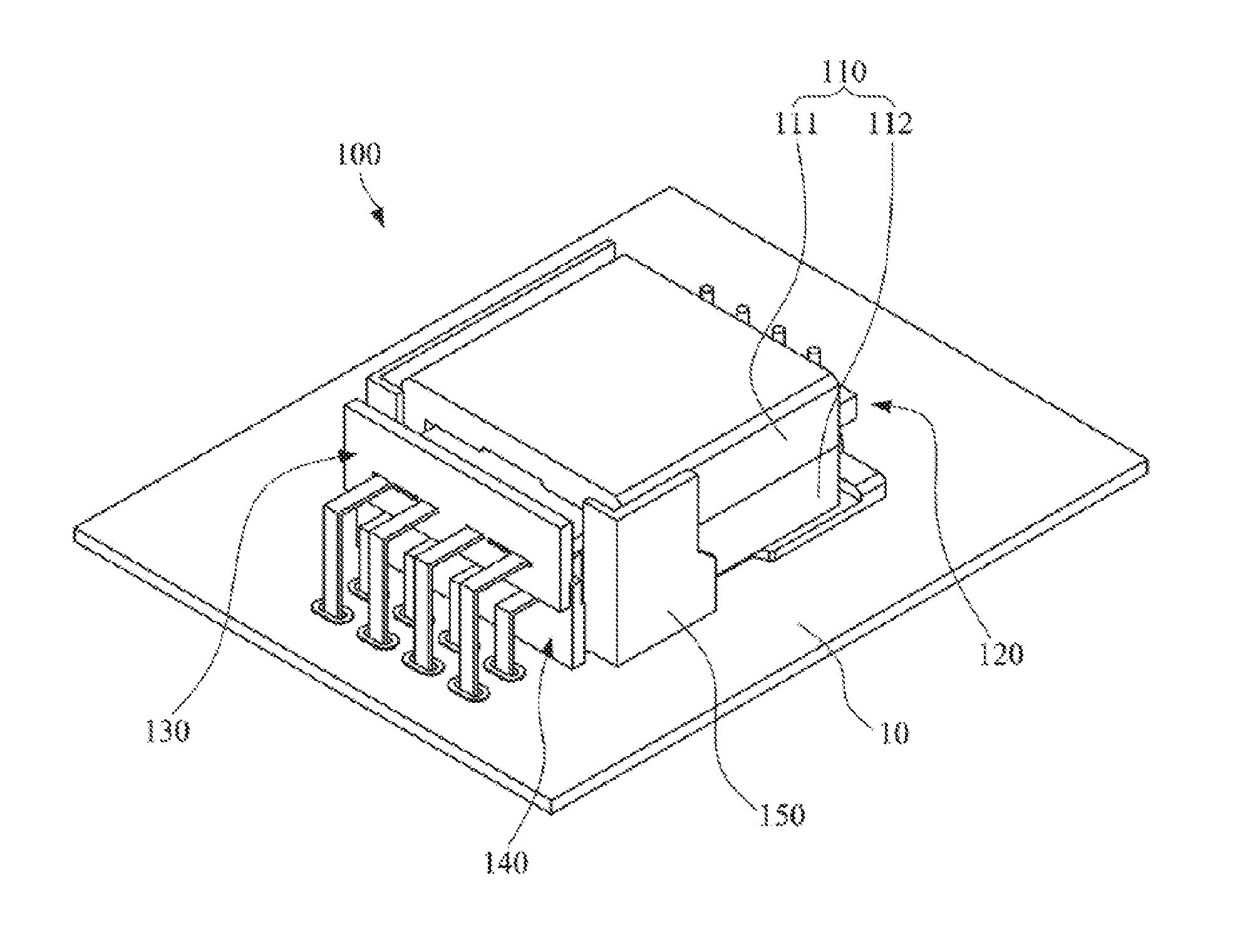
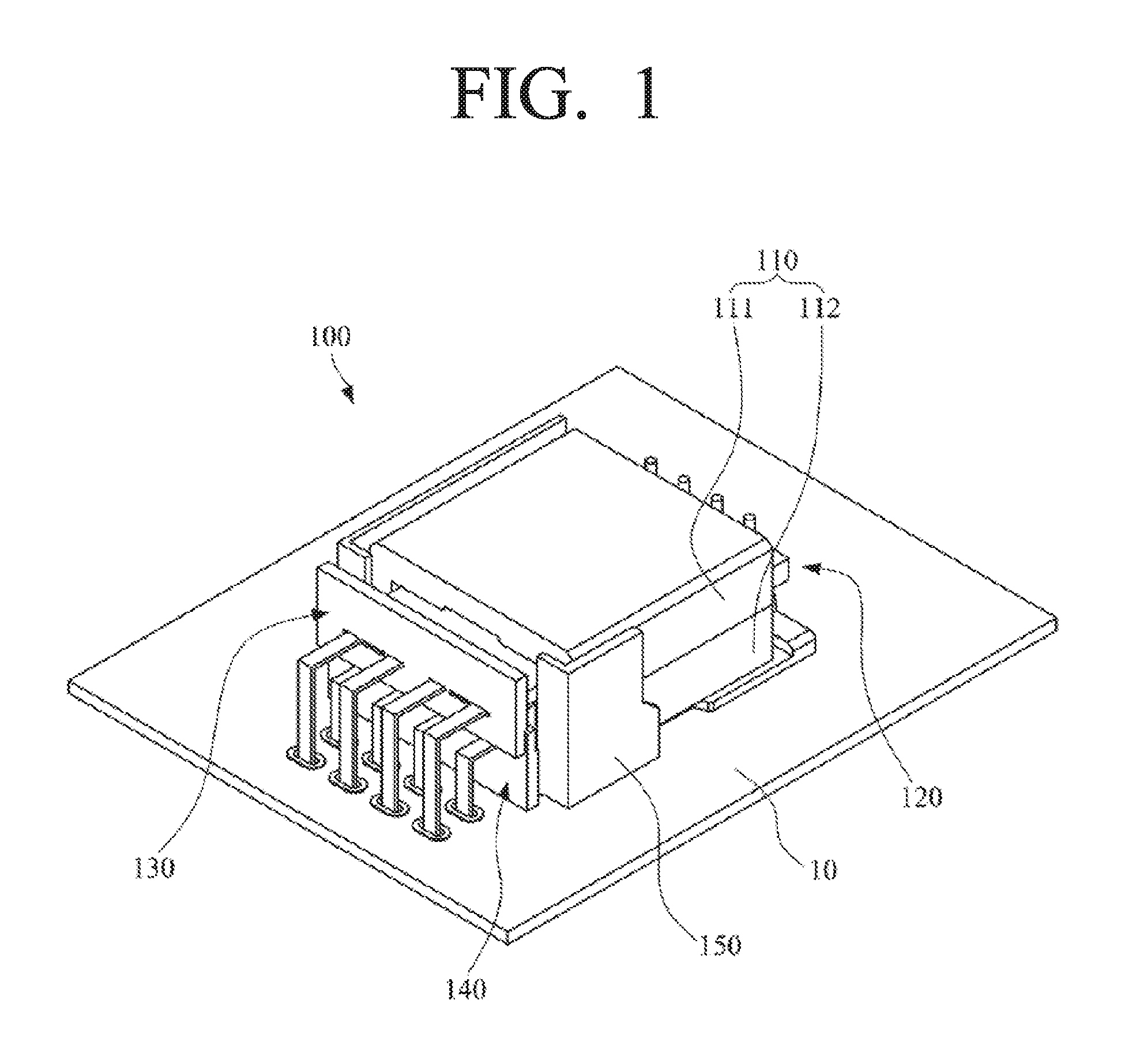
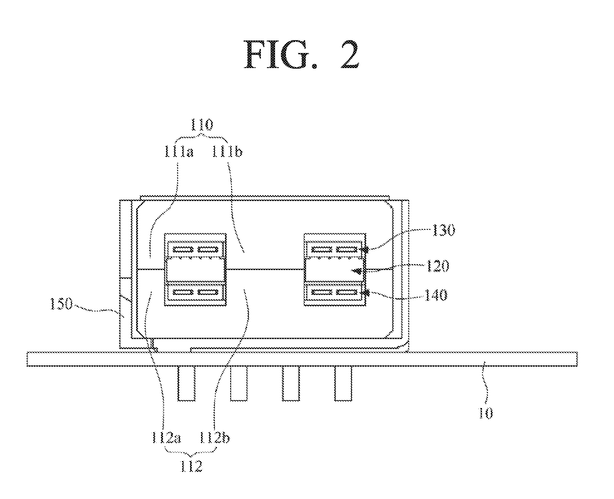
[0056]FIG. 1 is a perspective view of a transformer according to a first embodiment of the present disclosure, and FIG. 2 is a front cross-sectional view of the transformer of FIG. 1. FIG. 3 is an exploded perspective view of the transformer of FIG. 1, and FIG. 4 is a perspective view of upper and lower secondary coil modules extracted from the transformer of FIG. 3.

[0057]Referring to FIGS. 1 to 4, a transformer 100 according to a first embodiment of the present disclosure includes a magnetic core 110, a primary coil module 120, an upper secondary coil module 130, and a lower secondary coil module 140.

[0058]The magnetic core 110 is formed to have an inner space, and front and rear sides of the magnetic core 110 are formed in an open shape. Here, for convenience in explanation, front and rear directions are defined on the basis of the directions in which the primary coil module 120 and the upper and lower secondary coil modules 130 and 140 are drawn from the inside of the magnetic co...

second embodiment

[0102]FIG. 7 is a perspective view of a transformer according to a second embodiment of the present disclosure, and FIG. 8 is a side cross-sectional view of the transformer of FIG. 7. FIG. 9 is an exploded perspective view of the transformer of FIG. 7, and FIG. 10 is a perspective view of upper and lower secondary coil modules extracted from the transformer of FIG. 9.

[0103]Referring to FIGS. 7 to 10, a transformer 200 according to a second embodiment of the present disclosure includes a magnetic core 210, a primary coil module 220, an upper secondary coil module 230, and a lower secondary coil module 240. Here, the magnetic core 210 and the primary coil module 220 according to this embodiment may be constructed in the same manner as the magnetic core 110 and the primary coil module 120 according to the first embodiment.

[0104]An upper plate coil 236 has inner and outer end portions that are exposed from an upper insulation molded body 231 and an intermediate region wound in a spiral ...

third embodiment

[0114]FIG. 12 is a perspective view of a transformer according to a third embodiment of the present disclosure, and FIG. 13 is a side cross-sectional view of the transformer of FIG. 12. FIG. 14 is an exploded perspective view of the transformer of FIG. 12, and FIG. 15 is a perspective view of upper and lower secondary coil modules extracted from the transformer of FIG. 14.

[0115]Referring to FIGS. 12 to 15, a transformer 300 according to a third embodiment of the present disclosure includes a magnetic core 310, a primary coil module 320, an upper secondary coil module 330, and a lower secondary coil module 340. Here, the primary coil module 320 according to this embodiment may be constructed in the same manner as the primary coil module 120 according to the first embodiment.

[0116]An upper core 311 is formed in a manner that pairs of first legs 311a project from left and right edges of a lower surface of the upper core 311 to come in contact with left and right edges of an upper surfa...


PUM


Abstract

A transformer is provided, which includes a magnetic core, a primary coil module including a coil support arranged in the magnetic core and a primary coil formed on the coil support, an upper secondary coil module including an upper insulation molded body arranged on an upper portion of the primary coil module and an upper plate coil buried in the upper insulation molded body and arranged to face the primary coil, and a lower secondary coil module including a lower insulation molded body arranged on a lower portion of the primary coil module and a lower plate coil buried in the lower insulation molded body and arranged to face the primary coil.

Description

CROSS-REFERENCE TO RELATED APPLICATIONS[0001]This application claims priority from Korean Patent Application Nos. 10-2015-0109156 and 10-2015-0125713 filed on Jul. 31, 2015 and Sep. 4, 2015, respectively, in the Korean Intellectual Property Office, the disclosure of which is incorporated herein by reference in its entirety.BACKGROUND OF THE INVENTION[0002]Field of the Invention[0003]The present disclosure relates to a transformer provided in a power supply device or the like.[0004]Description of the Related Art[0005]A power unit is provided in a power supply device. A transformer provided in the power unit has a size that is about ⅓ of the overall size of the power unit. The transformer has a small number of components including a core, a bobbin, and coils. However, since a primary coil and a secondary coil provided in the transformer should be insulated from each other in order to secure a space for an insulation distance that is required between the coils and to satisfy the safety...

Claims


Application Information

Patent Timeline
IPC IPC(8): H01F27/32H01F27/28H01F41/12H01F27/24
CPCH01F27/32H01F41/12H01F27/28H01F27/24H01F27/2866H01F27/306H01F27/324H01F27/2804H01F27/2823H01F27/2847H01F27/325H01F2027/2819
Inventor PARK, GEUN-YOUNGJANG, BONG-HOEOM, JAE-GENNOH, YOUNG-SEUNGCHOI, HEUNG-GYOONKIM, HEUI-WOOK
Owner SOLUM CO LTD
Why Eureka
Try Eureka