X-ray generating apparatus and radiography system

a technology of generating apparatus and radiography, applied in the field of radiography system, can solve the problems of reducing reducing the service life so as to improve the durability of the x-ray generating apparatus

Active Publication Date: 2017-02-02
CANON KK
View PDF33 Cites 7 Cited by
  • Summary
  • Abstract
  • Description
  • Claims
  • Application Information

AI Technical Summary

Benefits of technology

[0007]The present invention provides a means by which the d

Problems solved by technology

However, the x-ray generating apparatus described in U.S. Pat. No. 7,949,099 may lack durability because the insulating me

Method used


Image

  • X-ray generating apparatus and radiography system
  • X-ray generating apparatus and radiography system
  • X-ray generating apparatus and radiography system

Examples


example 1

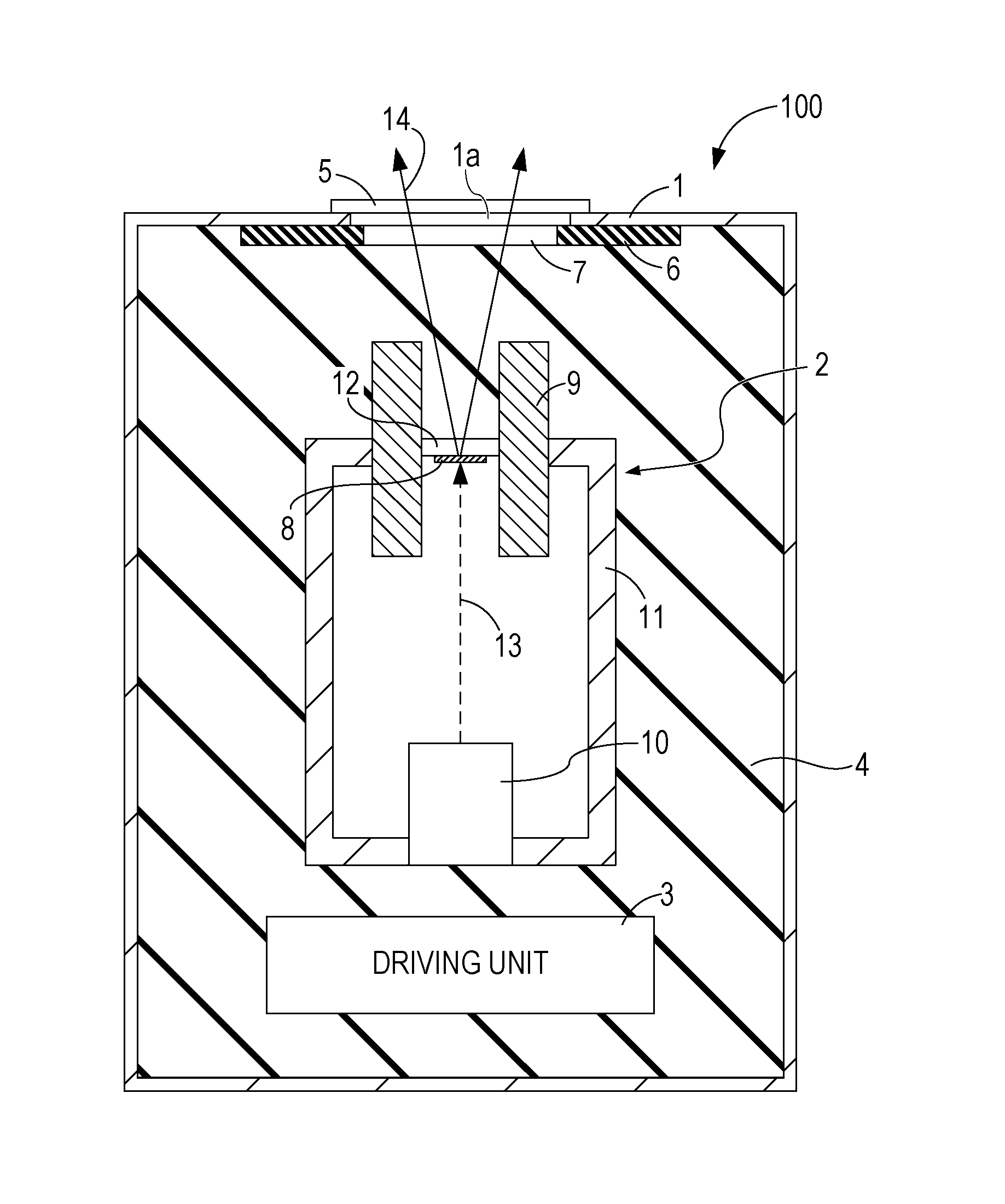
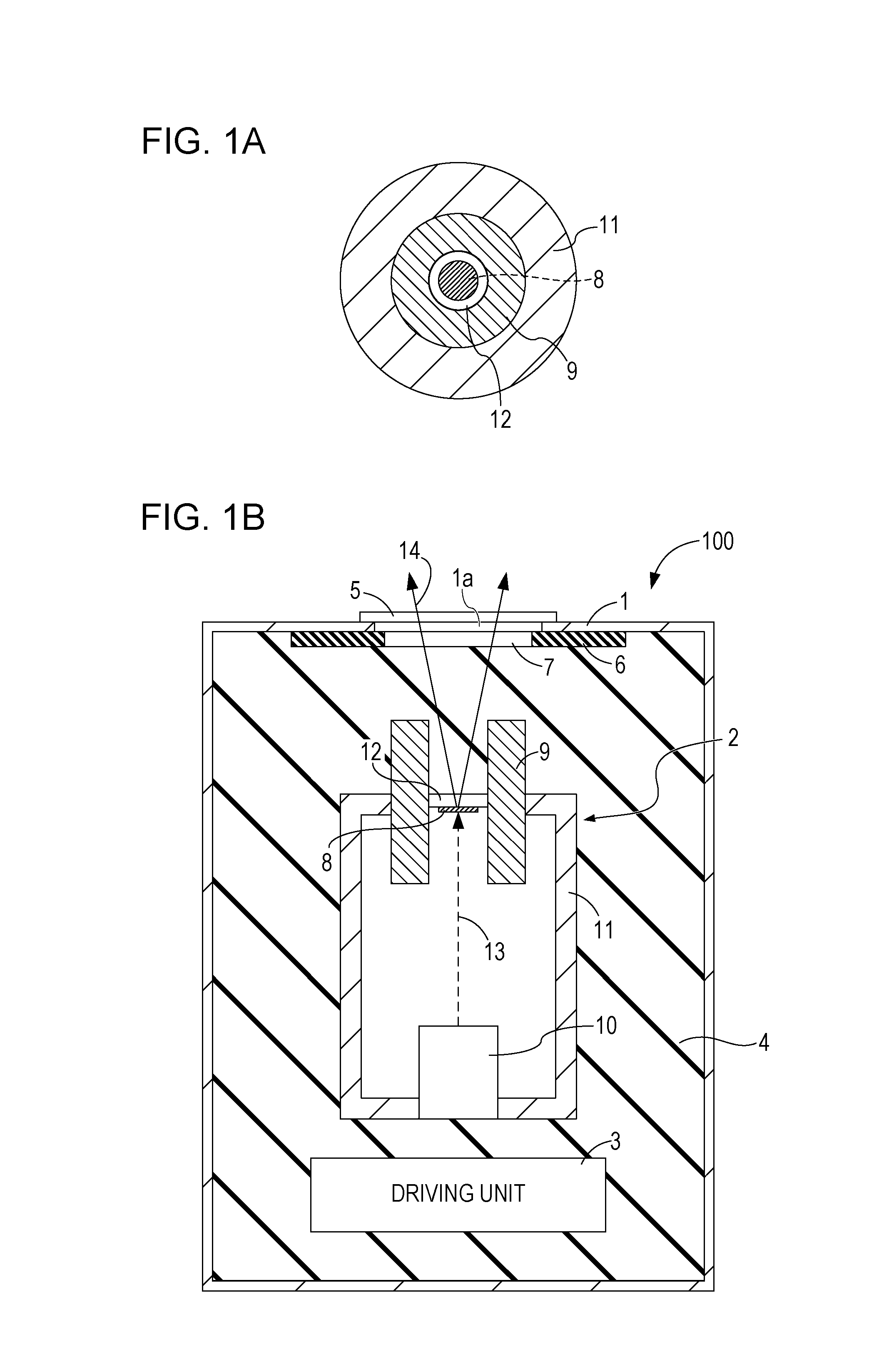
[0049]Regarding Example 1, the X-ray generating apparatus 100 illustrated in FIG. 3 is produced. In Example 1, the vacuum chamber 11 is an alumina cylinder which is 30 mm in inner diameter, 50 mm in outer diameter, and 80 mm in length. The electron source 10 is a thermal-electron gun of an impregnated cathode, is contained in the vacuum chamber 11, and is joined to the vacuum chamber 11 by silver soldering. As the target layer 8, tungsten which is 5 μm in thickness and 4 mm in diameter is selected and formed as a layer on one side of the first window 12 by CVD. To establish an electrical connection between the target layer 8 and the shielding member 9, a part of a peripheral portion of the target layer 8 is extended to a peripheral portion of the first window 12. As the first window 12, diamond which is 6 mm in diameter and 2 mm in thickness is selected. The shielding member 9 is a tungsten cylinder which is 6 mm in inner diameter, 30 mm in outer diameter, and 30 mm in length. The f...

example 2

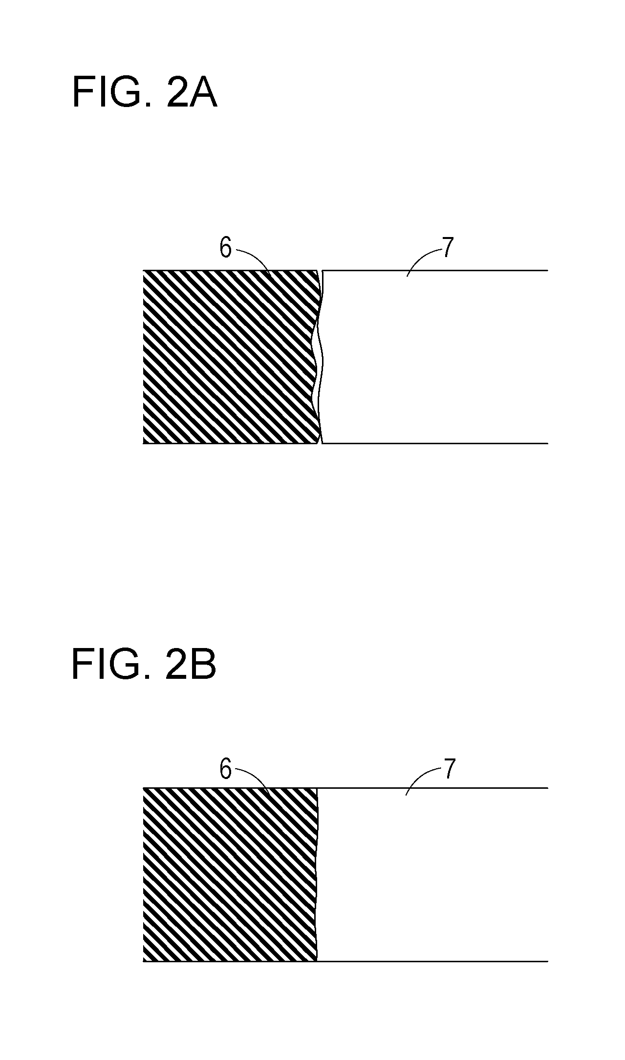
[0054]An X-ray generating apparatus is produced to have the same configuration as that of Example 1 except that a step is formed in a contact surface of the third window 7 with the insulating member 6 as illustrated in FIG. 4A. In the third window 7, d1 is set to be 35 mm, d2 is set be 30 mm, and the thickness t1 of d1 and the thickness t2 of d2 are both 2 mm. The X-ray generating apparatus is driven under the same condition as that of Example 1 except that the tube voltage of a continuous operation condition is 120 kV. As a result, no electrical discharge occurs and the third window 7 is replaced without problems. In Example 2, an effect of higher voltage withstanding property than that of Example 1 is obtained.

example 3

[0055]An X-ray generating apparatus is produced in the same manner as in Example 1 except that the third window 7 is formed of 4-mm-thick PMMA used for the insulating member 6 in Example 1 and the insulating member 6 is formed of a 4-mm-thick glass epoxy plate. As illustrated in FIG. 6, the X-ray absorption coefficient of PMMA used in this example is smaller than that of glass epoxy in the range of X-ray energy from 40 keV to 120 keV. Therefore, the integrated value of the X-ray absorption coefficient in that range is smaller in the third window 7 than in the insulating member 6 in this example. The product of the X-ray absorption coefficient and the thickness is also smaller in the third window 7 than in the insulating member 6. In this example, an effect is obtained that the third window 7 transmits the X-ray and unnecessary X-ray is absorbed by the insulating member 6. Since the X-ray absorption coefficient of the third window 7 is smaller in this example (PMMA) than in Example 1...


PUM


Abstract

Provided is an X-ray generating apparatus, which includes: an X-ray generating tube configured to emit X-rays through a first window; an outer case configured to contain the X-ray generating tube and provided with a second window transmitting the X-rays at a position facing the first window; an insulating fluid with which an unoccupied space of the outer case is filled; an insulating member located between the first window and the second window and provided with an opening in an irradiation area of the X-ray through the first window; and an insulating third window removably fit into the opening of the insulating member, wherein a linear expansion coefficient of the third window is greater than a linear expansion coefficient of the insulating member, and the third window and the first window face each other via a gap through which the insulating fluid is flowable.

Description

BACKGROUND OF THE INVENTION[0001]Field of the Invention[0002]The present invention relates to a radiography system applicable to medical equipment, a nondestructive inspection apparatus and the like, and relates also to an X-ray generating apparatus employed in the radiography system.[0003]Description of the Related Art[0004]A radiography system in which an X-ray generating apparatus is incorporated, irradiates a subject with X-rays from an X-ray generating apparatus, and detects the X-rays penetrating the subject with an X-ray detector. The X-ray generating apparatus used here includes an X-ray generating tube inside an outer case. The X-ray generating tube accelerates electrons emitted from an electron source by a tube voltage, and irradiates a target made of metal, such as tungsten, with the electrons to generate X-rays.[0005]In order to generate desirable X-rays for X-ray radiography by the X-ray generating tube, it is necessary to apply the tube voltage in the range of 40 kV to...

Claims


Application Information

Patent Timeline
IPC IPC(8): H01J35/18G01N23/04H05G1/30A61B6/00
CPCH01J35/18A61B6/40H01J2235/1262H05G1/30G01N23/04A61B6/4488H05G1/06H01J35/064H01J35/112H01J35/02H01J35/025H01J35/16
Inventor TSUNODA, KOICHIYAMAZAKI, KOJIAOKI, SHUJIUEDA, KAZUYUKI
Owner CANON KK
Why Eureka
Try Eureka