Endoscope with Variable Profile Tip

a technology of endoscope and tip, which is applied in the field of single-use electronic endoscope, can solve the problems of limiting post-surgical patient activity, operative or therapeutic arthroscopic surgery has limitations, and takes significant time to heal, so as to facilitate therapeutic endoscope use, avoid delays and costs, and good visualization

Active Publication Date: 2017-02-09
ENLIGHTENVUE INC
View PDF6 Cites 43 Cited by
  • Summary
  • Abstract
  • Description
  • Claims
  • Application Information

AI Technical Summary

Benefits of technology

[0019]Tools can be passed from the hub, along the shaft within a working channel, and to the distal tip. A variable profile working channel at the distal tip allows one or more tools to pass the image sensor and into its field of view without increasing the overall size of the endoscope at the proximal shaft. The working channel changes from a relatively compact, generally noncircular cross-sectional shape to a different and enlarged cross-sectional shape. This shape change accommodates tools passing through the working channel, but also allows the endoscope to have a relatively low profile when first inserted into the patient.
[0023]The cross-section differs at another point along the distal tip. This second cross-section has the sensor, the working channel, the flushing lumen and the light-guide. Both the working channel and the flushing lumen in this second cross-section have independently variable profiles. Each transforms from a generally noncircular, low-profile configuration to an enlarged-profile configuration. The enlarged-profile configuration allows one or more tools to pass through the working channel or permits liquid to travel through the flushing lumen.
[0027]The described electronic endoscopes are useful for various operative or therapeutic procedures (e.g., arthroscopy, gall stone intervention, gynecologic endoscopy, kidney stone intervention, otolaryngologic endoscopy, and urologic endoscopy). Such disposable endoscopes do not need re-sterilization, and can provide good visualization in a relatively small package, because the portion of the endoscope inserted into the patient has an outer diameter of about 2 mm or less. This facilitates therapeutic endoscopic use by general practice doctors in their offices on an outpatient basis and avoids delays and costs associated with scheduling procedures to occur in hospital operating rooms.

Problems solved by technology

However, large surgical wounds cause significant patient pain, involve use of powerful anesthetics and analgesics such as narcotics to keep the patient comfortable during and after surgery, often take significant time to heal and limit post-surgical patient activity (particularly if muscle is cut to access the treatment area).
Such operative or therapeutic arthroscopic surgery has limitations.
Operational arthroscopic procedures can have life-threatening risks.
The complex design of some endoscopes impedes the ability to clean, disinfect, and sterilize these reusable devices.
Previously known endoscopes suffer a number of disadvantages, including significant initial cost and the need for sterilization after each use.
Such sterilization procedures are time consuming and lead to further expense.

Method used


Image

  • Endoscope with Variable Profile Tip
  • Endoscope with Variable Profile Tip
  • Endoscope with Variable Profile Tip

Examples


example 1

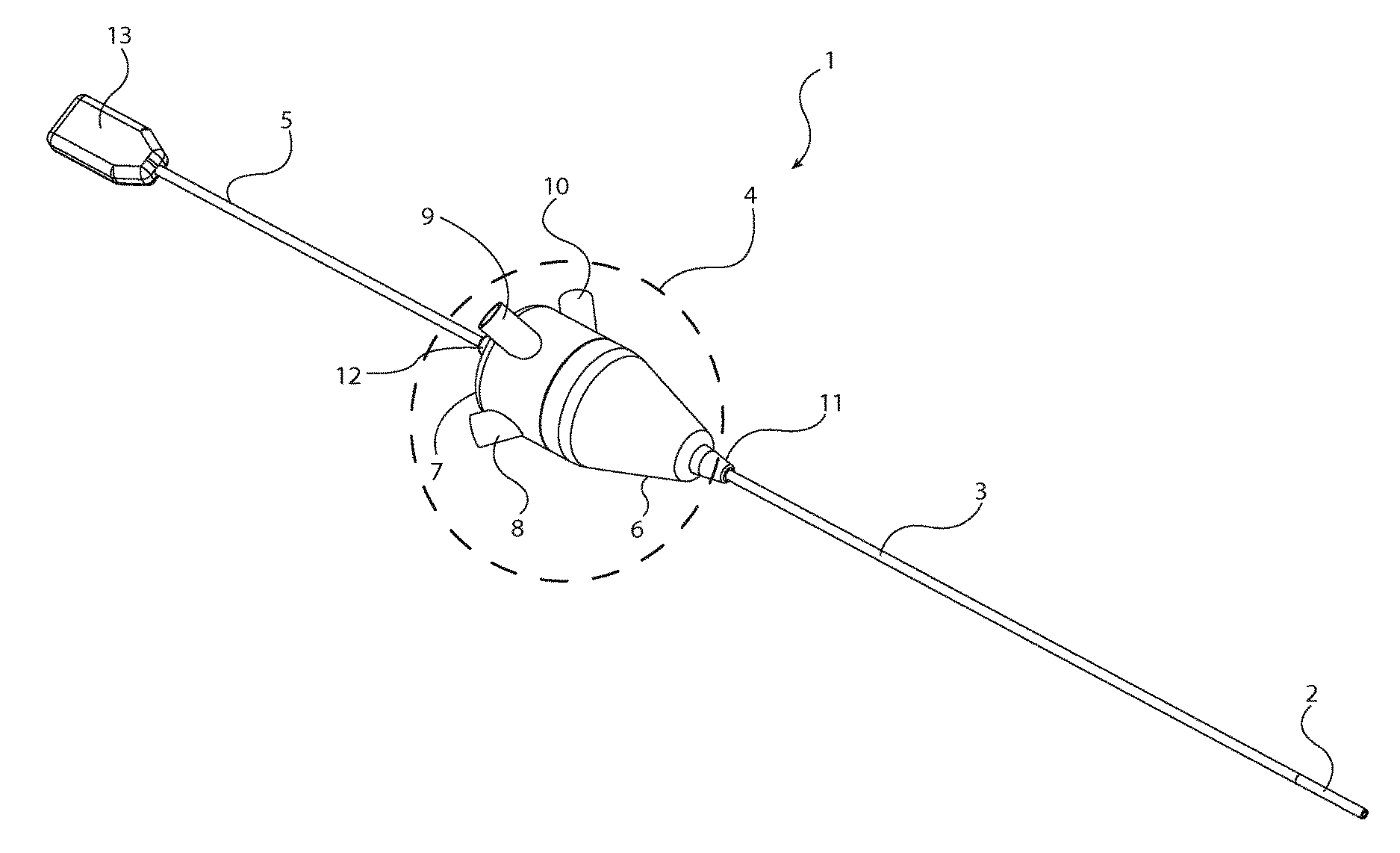
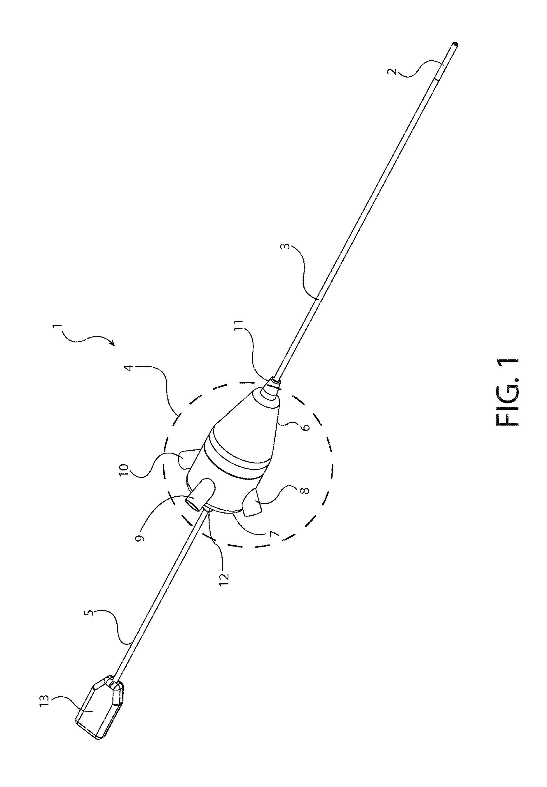
[0102]A 2 mm endoscope with expandable working channel and an LED light source in the hub similar to that shown in FIG. 1 is formed as described below. Two injection-molded ABS pieces 6, 7 (available from Dow Chemical) form the hub enclosure.

[0103]Insert cable assembly 5 with USB connector 13 (available from Molex Connector Corp.) into a strain relief tube 12 and then into a proximal opening in the proximal hub enclosure 7. The strain relief tube 12 is an injection molded component made from Shore A 60 TPE. The cable assembly 5 is electrically connected to a printed circuit assembly (PCA) 61.

[0104]PCA 61 is a small, multi-layer printed circuit board with surface mount integrated circuits to convert USB signals and communications to / from the camera into the signal levels and timing required by the camera specifications. The PCA 61 is affixed to the proximal hub enclosure 7 using four screws 73. See FIG. 7.

[0105]The proximal hub enclosure has an opening for the working channel. A work...

example 2

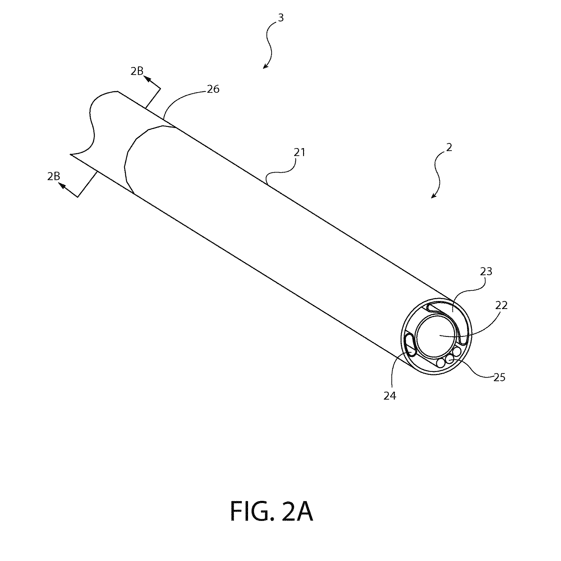
[0117]An endoscope similar to that described in Example 1 is formed with a variable profile flushing lumen 24 in addition to the variable profile working channel as illustrated in FIG. 2A. A 30 cm length of TPE tubing (Vention Medical PEBAX® tubing catalog number 115-1289; 0.0.279 mm ID, 0.1143 mm wall thickness, 0.51 mm OD, Shore A 63) forms the flushing lumen 24. The process for making the endoscope is similar to Example 1. Differences are discussed below.

[0118]Place the PEBAX® tubing adjacent to the working channel assembly 23 / 28 / 35, and push the proximal end of tubing over a barb fitting the LUER-LOK® lock connector 8. This secures the flushing lumen 24 to the proximal hub enclosure 7. Position the distal end of the flushing lumen tubing 24 adjacent the camera 22 within the expandable tip before sealing the tip.

example 3

[0119]An endoscope similar to that described in Example 2 except the flushing lumen 24 is made from a non-expandable material. Instead of PEBAX® tubing, the flushing lumen 24 is made from polyimide tubing (Vention Medical catalog number 141-0023; 0.508 mm OD, 0.457 mm ID).

[0120]Even though the material itself is non-expandable, the flushing lumen is manufactured to provide that feature. At the distal end, heat press an 8 mm length of the polyimide tubing to form creases and a flattened end. This enables the polyimide tubing to curve around camera 22 inside the expandable outer cover 21. Place a proximal end of the polyimide tubing over the barbed connector of the commercially available connector 8 (a LUER-LOK® component) and affix it with Methyl-Ethyl-Ketone solvent.

[0121]In use, the creased and flattened distal tip of the flushing lumen 24 expands as fluid passes within the flushing lumen 24. This, in turn, expands the outer cover 21. See FIGS. 3 and 4.


PUM


Abstract

A single-use electronic endoscope has a hub, a shaft extending from the hub, flexible or rigid as desired, and an expandable distal tip extending from the shaft. Within the distal tip, an image sensor provides a field of view external from the endoscope. Illuminating elements or light guides within the distal tip emit light to illuminate the field of view. The distal tip also has a variable profile working channel that permits tools to be passed from the hub and into the field of view. The expandable working channel changes cross-sectional shape from a generally noncircular shape to a shape to accommodate the cross-sectional shape of the tool when expanded.

Description

BACKGROUND OF THE INVENTION[0001]1. Field of the Invention[0002]The described technology relates generally to devices and methods for imaging within a body lumen, cavity or other enclosed space, and, more particularly, it relates to a single-use electronic endoscope for various uses (e.g., for arthroscopic knee surgery).[0003]2. Description of the Related Art[0004]Diagnosing and treating patients often involves examination of internal organs and structures. In “open surgery,” a large surgical cut or incision is made in the patient's skin and flesh. Doing so permits the doctor to see directly into and access the area being treated. However, large surgical wounds cause significant patient pain, involve use of powerful anesthetics and analgesics such as narcotics to keep the patient comfortable during and after surgery, often take significant time to heal and limit post-surgical patient activity (particularly if muscle is cut to access the treatment area).[0005]To avoid disturbing near...

Claims


Application Information

Patent Timeline
Patent Type & Authority Applications(United States)
IPC IPC(8): A61B1/018A61B1/12A61B1/06A61B1/00A61B1/05
CPCA61B1/018A61B1/00103A61B1/12A61B1/06A61B1/05A61B1/005A61B1/04A61B1/00114A61B1/00121A61B1/012A61B1/015A61B1/0008A61B1/00082A61B1/00135A61B1/00078
Inventor KUCHARSKI, ROBERT C.BLOOM, PAUL I.BASADONNA, GIACOMOBLANKENSHIP, LARRY O.BUCKNAM, LAURA E.
Owner ENLIGHTENVUE INC
Why Eureka
Try Eureka