Slip-Controllable Vehicle Brake System
a brake system and control technology, applied in the field of vehicle brake systems, can solve problems such as more difficult starting, and achieve the effect of large and heavy construction
- Summary
- Abstract
- Description
- Claims
- Application Information
AI Technical Summary
Benefits of technology
Problems solved by technology
Method used
Image
Examples
Embodiment Construction
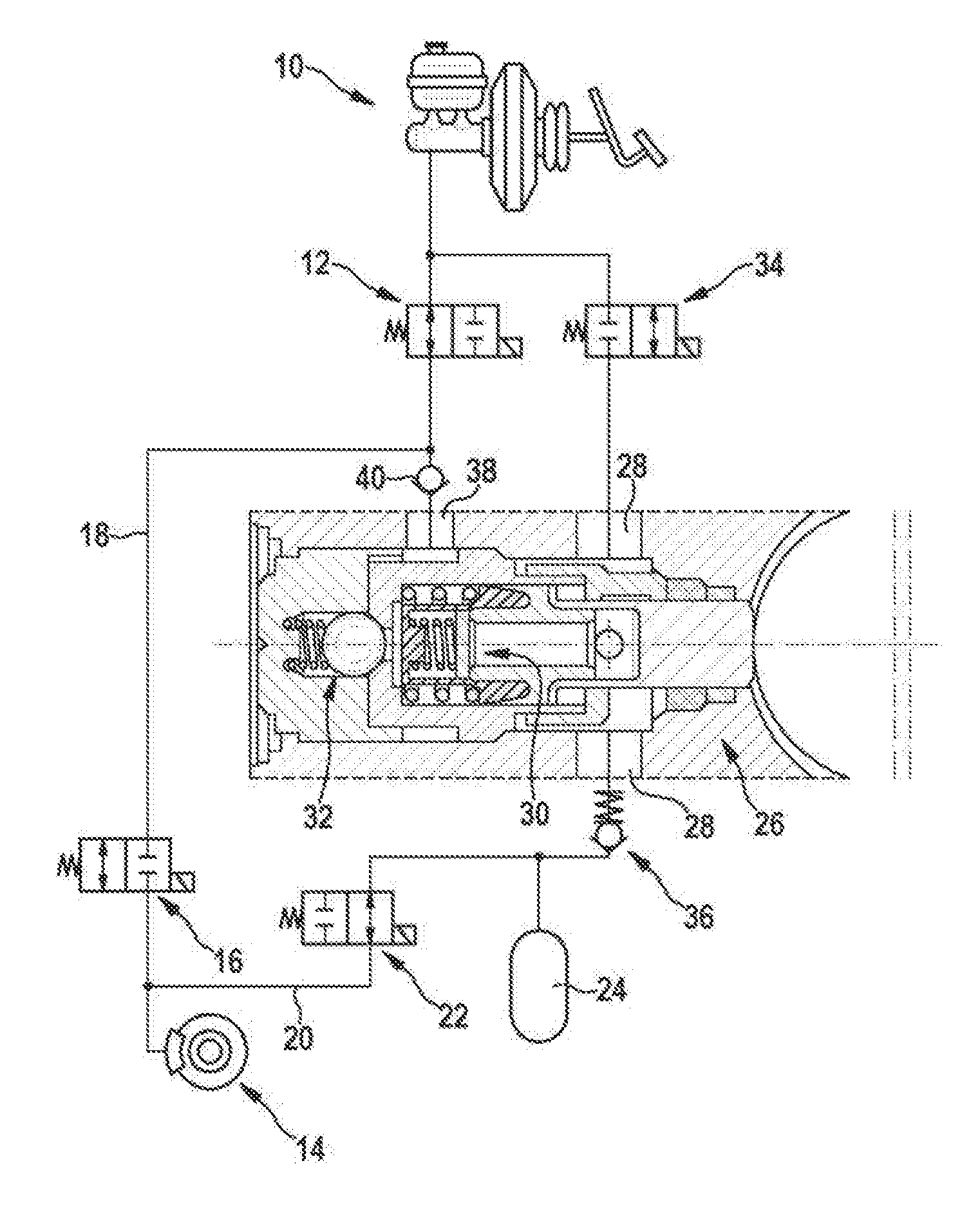
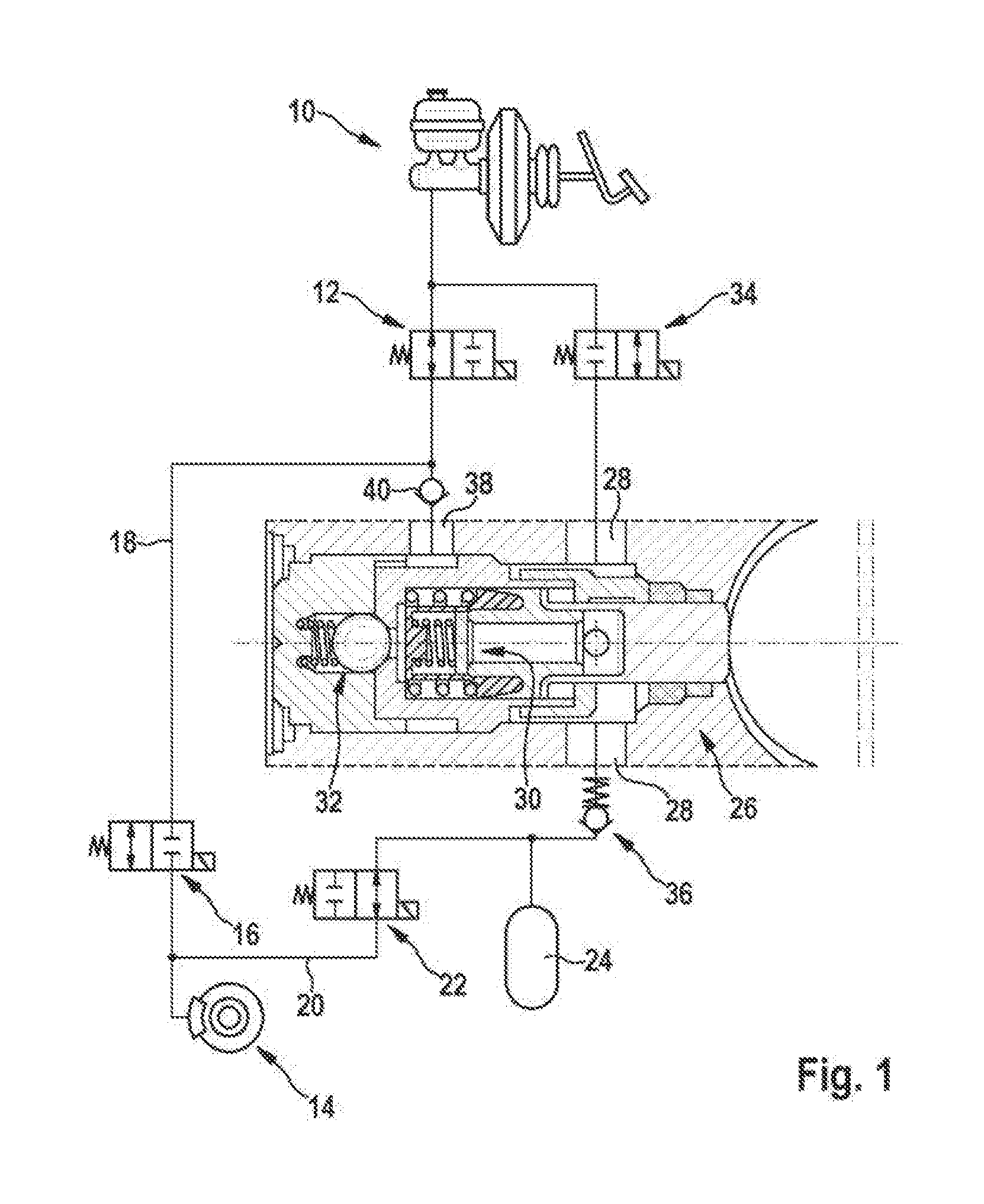
[0013]Using circuit symbols, the hydraulic circuit diagram represented in FIG. 1 shows a brake circuit of a vehicle brake system with wheel slip control, substantial parts of which are known. Among other things, this brake circuit comprises a brake master cylinder 10 actuated physically by the driver. A connection of the brake circuit to the brake master cylinder 10 can be controlled by way of a switch-over valve 12. The switch-over valve 12 is open in its basic position and, actuated by a solenoid, can be switched into a closed position. In the closed position of the switch-over valve 12 the driver is unable to vary the brake pressure on a wheel brake 14 connected to the brake circuit.
[0014]The brake circuit branches off downstream of the switch-over valve 12. A line branch leads via a pressure build-up valve 16, in the form of a normally open 2 / 2-way directional control valve, to the wheel brake 14 and thereby forms the inlet 18 to the wheel brake.
[0015]A return 20 from the inlet ...
PUM
 Abstract
Description
Claims
Application Information
 - R&D
- Intellectual Property
- Life Sciences
- Materials
- Tech Scout
- Unparalleled Data Quality
- Higher Quality Content
- 60% Fewer Hallucinations
Browse by: Latest US Patents, China's latest patents, Technical Efficacy Thesaurus, Application Domain, Technology Topic, Popular Technical Reports.
© 2025 PatSnap. All rights reserved.Legal|Privacy policy|Modern Slavery Act Transparency Statement|Sitemap|About US| Contact US: help@patsnap.com


