Connector and gas-liquid separator for combined electric submersible pumps and beam lift or progressing cavity pumps

Active Publication Date: 2017-02-16
BOARD OF RGT THE UNIV OF TEXAS SYST
View PDF1 Cites 6 Cited by
  • Summary
  • Abstract
  • Description
  • Claims
  • Application Information

AI Technical Summary

Benefits of technology

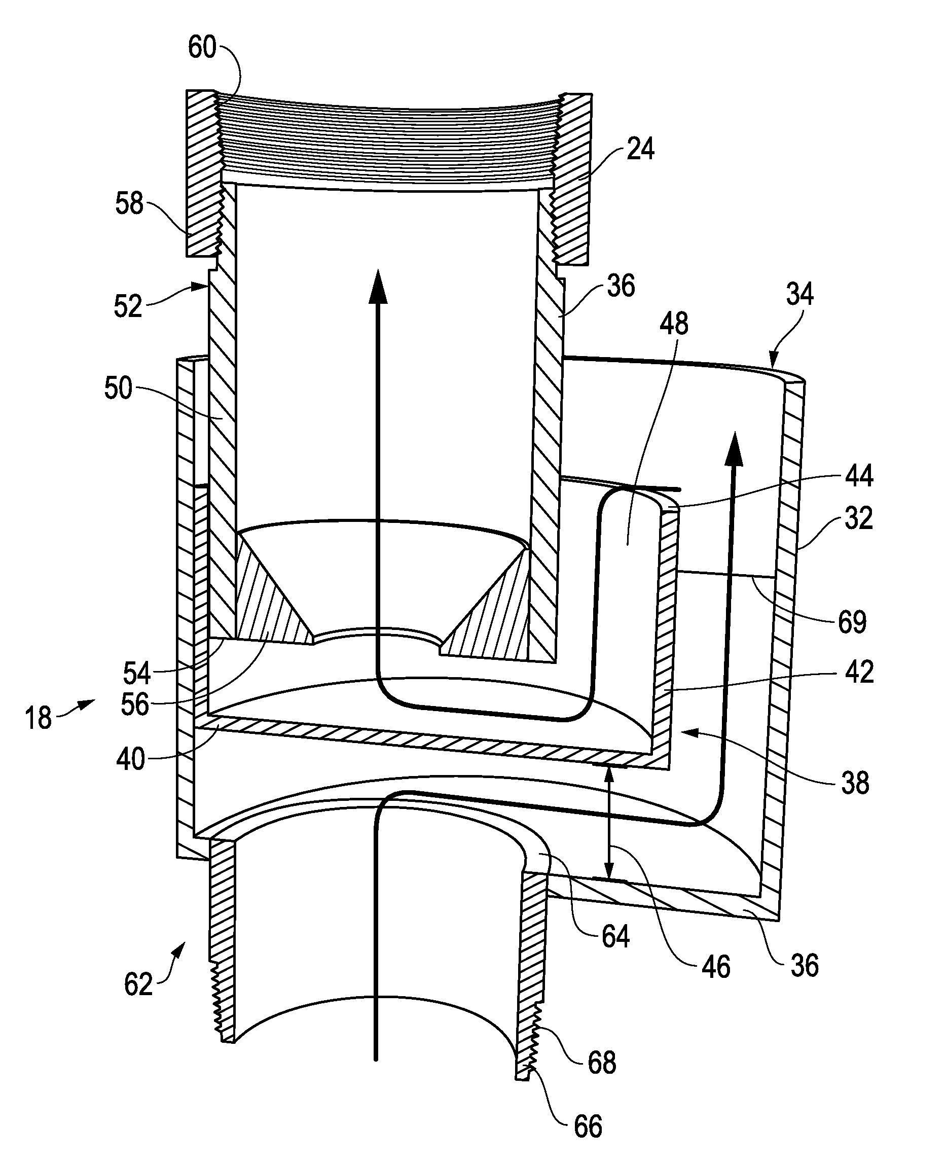
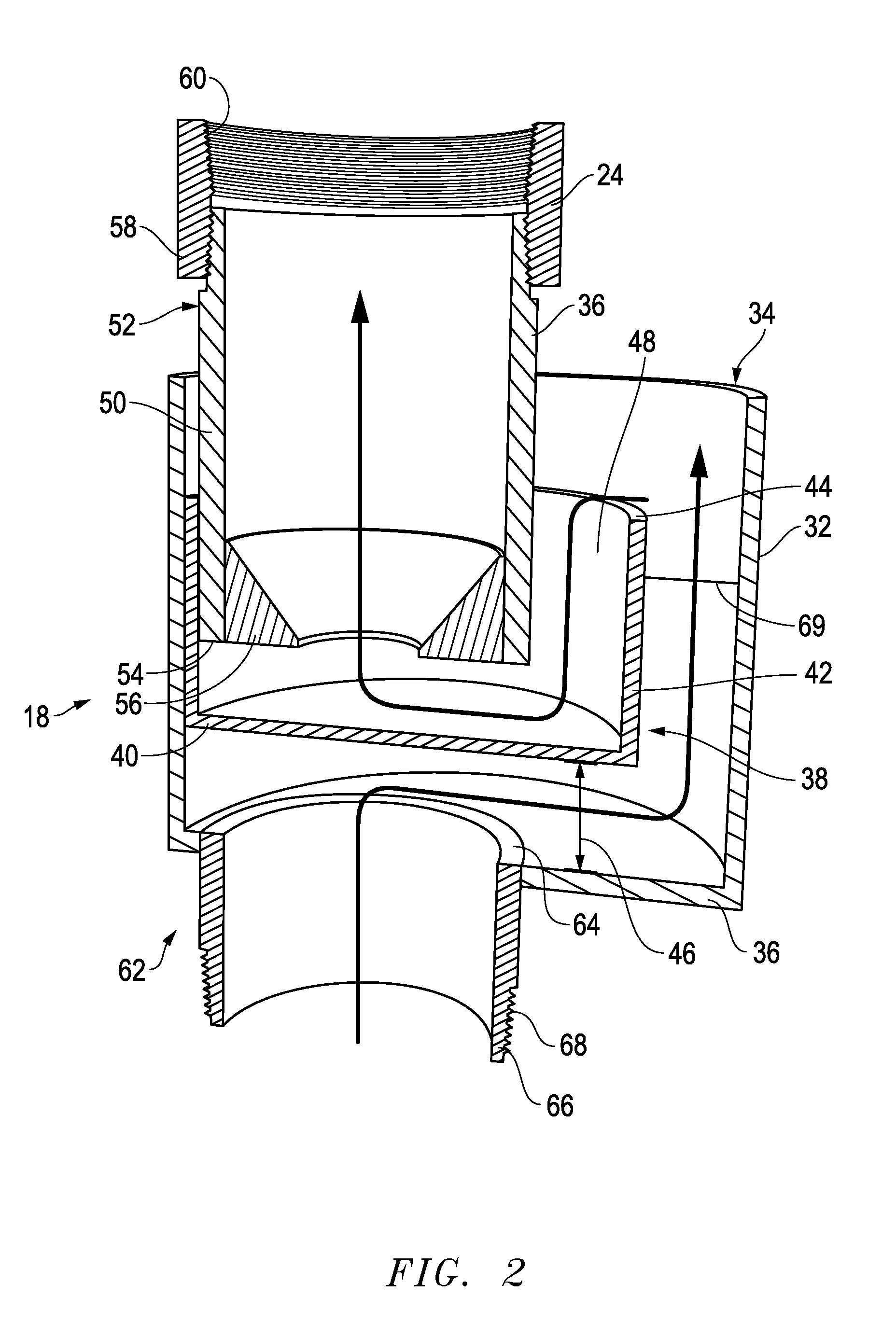
[0007]The present invention provides a downhole assembly of an artificial-lift system. The connector is a three concentric tube device with a conventional size piece of tubing as the inner of the three tubes. This tube connects the tubing which extends to the surface to the tubing that extends into the well where the ESP is located. The tubes are made such that flow of fluids from the ESP enters the bottom of the connector through the inner tube and are diverted into the largest of the three concentric tubes located as the outside tube. The relatively large space between the inside tube and the outside tube allows for the gas to separate from the liquid. This may be enhanced by the addition of an optional foam breaker across the opening of the annulus formed between the inside and outside tube. The gas continues to rise to the surface in the tubing-casing annulus. The liquid now can enter, by gravity, the third tube that is placed outside the inner tube (the tubing) and the large external tube. This third concentric tube is not as long as the large outer tube and is connected at the bottom to become the entrance to the pump intake for the beam pump or PCP. The pump intake for the beam pump or PCP is a part of the smallest inner tube of the connector.
[0008]The present invention provides a system usable with a well. The connector is a three concentric tube device with a conventional size piece of tubing as the inner of the three tubes. This tube connects the tubing which extends to the surface to the tubing that extends into the well where the ESP is located. The tubes are made such that flow of fluids from the ESP enters the bottom of the connector through the inner tube and are diverted into the largest of the three concentric tubes located as the outside tube. The relatively large space between the inside tube and the outside tube allows for the gas to separate from the liquid.

Problems solved by technology

During the process of hydrocarbon production the natural pressure of a reservoir eventually decreases to the po

Method used


Image

  • Connector and gas-liquid separator for combined electric submersible pumps and beam lift or progressing cavity pumps
  • Connector and gas-liquid separator for combined electric submersible pumps and beam lift or progressing cavity pumps
  • Connector and gas-liquid separator for combined electric submersible pumps and beam lift or progressing cavity pumps

Examples


Embodiment Construction

[0013]While the making and using of various embodiments of the present invention are discussed in detail below, it should be appreciated that the present invention provides many applicable inventive concepts that can be embodied in a wide variety of specific contexts. The specific embodiments discussed herein are merely illustrative of specific ways to make and use the invention and do not delimit the scope of the invention.

[0014]To facilitate the understanding of this invention, a number of terms are defined below. Terms defined herein have meanings as commonly understood by a person of ordinary skill in the areas relevant to the present invention. Terms such as “a”, “an” and “the” are not intended to refer to only a singular entity, but include the general class of which a specific example may be used for illustration. The terminology herein is used to describe specific embodiments of the invention, but their usage does not delimit the invention, except as outlined in the claims.

[...


PUM


Abstract

The present invention provides a gas-liquid separator/connector having three concentric tube device made such that flow of fluids from a ESP enters the bottom and are diverted into the largest of the three concentric tubes located as the outside tube. The relatively large space between the inside tube and the outside tube allows for the gas to separate from the liquid. The gas continues to rise to the surface in the tubing-casing annulus. The liquid now can enter by gravity the third tube that is placed outside the inner tube (the tubing) and the large external tube. This third concentric tube is not as long as the large outer tube and is connected at the bottom to become the entrance to the pump intake for the beam pump or PCP. The pump intake for the beam pump or PCP is a part of the smallest inner tube of the connector.

Description

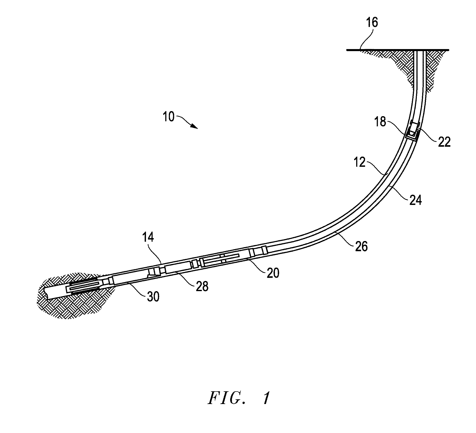
TECHNICAL FIELD OF THE INVENTION[0001]The present invention relates generally to methods and compositions used in the production of hydrocarbons and more specifically to methods and compositions for connecting and gas-liquid separator for combined electric submersible pumps (ESP) and beam lift or progressing cavity pumps (PCP).BACKGROUND OF THE INVENTION[0002]Without limiting the scope of the invention, its background is described in connection with a downhole apparatus and method used in hydrocarbon production, and in particular to a downhole apparatus and method that improves the rate of production of hydrocarbons using a combination of artificial-lift techniques.[0003]During the process of hydrocarbon production the natural pressure of a reservoir eventually decreases to the point that the pressure in the reservoir may become too low to force fluid from the producing zone to the surface. In response to this reduced pressure artificial-lift techniques may be required. In addition,...

Claims


Application Information

Patent Timeline
IPC IPC(8): E21B43/38F04D29/70E21B43/12
CPCE21B43/38F04D29/708E21B43/128E21B43/127E21B43/12
Inventor BOMMER, PAUL M.
Owner BOARD OF RGT THE UNIV OF TEXAS SYST
Why Eureka
Try Eureka