Combustor burner arrangement

a combustor and burner technology, applied in the direction of burners, combustion processes, lighting and heating apparatus, etc., can solve the problems of carbon deposits forming, affecting the performance of combustor systems, and affecting so as to prevent carbon deposits forming, and improve the reliability of igniting fuel

Active Publication Date: 2017-02-16
SIEMENS ENERGY GLOBAL GMBH & CO KG
View PDF10 Cites 4 Cited by
  • Summary
  • Abstract
  • Description
  • Claims
  • Application Information

AI Technical Summary

Benefits of technology

[0005]One objective of the present invention is to prevent carbon deposits forming on components. Another objective is to prevent carbon deposits forming on a fuel lance of a combustor. Another object is to improve the reliability of igniting the fuel in a combustor. Another objective is to improve the entrainment of fuel droplets in an air flow. Another objective is to improve the atomisation of liquid fuel in a combustor. Another objective is to prevent liquid fuel contacting a surface within the combustor. Another objective is to reduce or prevent scheduled or unscheduled shut down of the engine for maintenance attributed to replacing or cleaning combustor components subject to carbon deposits and particularly the liquid fuel lance.

Problems solved by technology

Gas turbines including dry low emission combustor systems can have difficulty lighting and performing over a full load range when using liquid fuels.
If the fuel droplets contact a surface this can lead to carbon deposits building up or lacquers forming and which can alter airflow characteristics or even block air and / or fuel supply holes.
This liquid pilot injection lance is in a region prone to liquid fuel contact and as a result tends to incur carbon deposits.
These carbon deposits block the air assistance holes and subsequently prevent successful atomisation of the fuel.
Poor atomisation of the pilot fuel also causes problems with ignition of the fuel at start-up.
This is a common fault with gas turbine fuel injection systems and carbon build up is a common problem.
This is undesirable because such replacement is expensive, causes the gas turbine to be off-line halting supply of electricity or power for example, and can be unscheduled.

Method used


Image

  • Combustor burner arrangement
  • Combustor burner arrangement
  • Combustor burner arrangement

Examples


Embodiment Construction

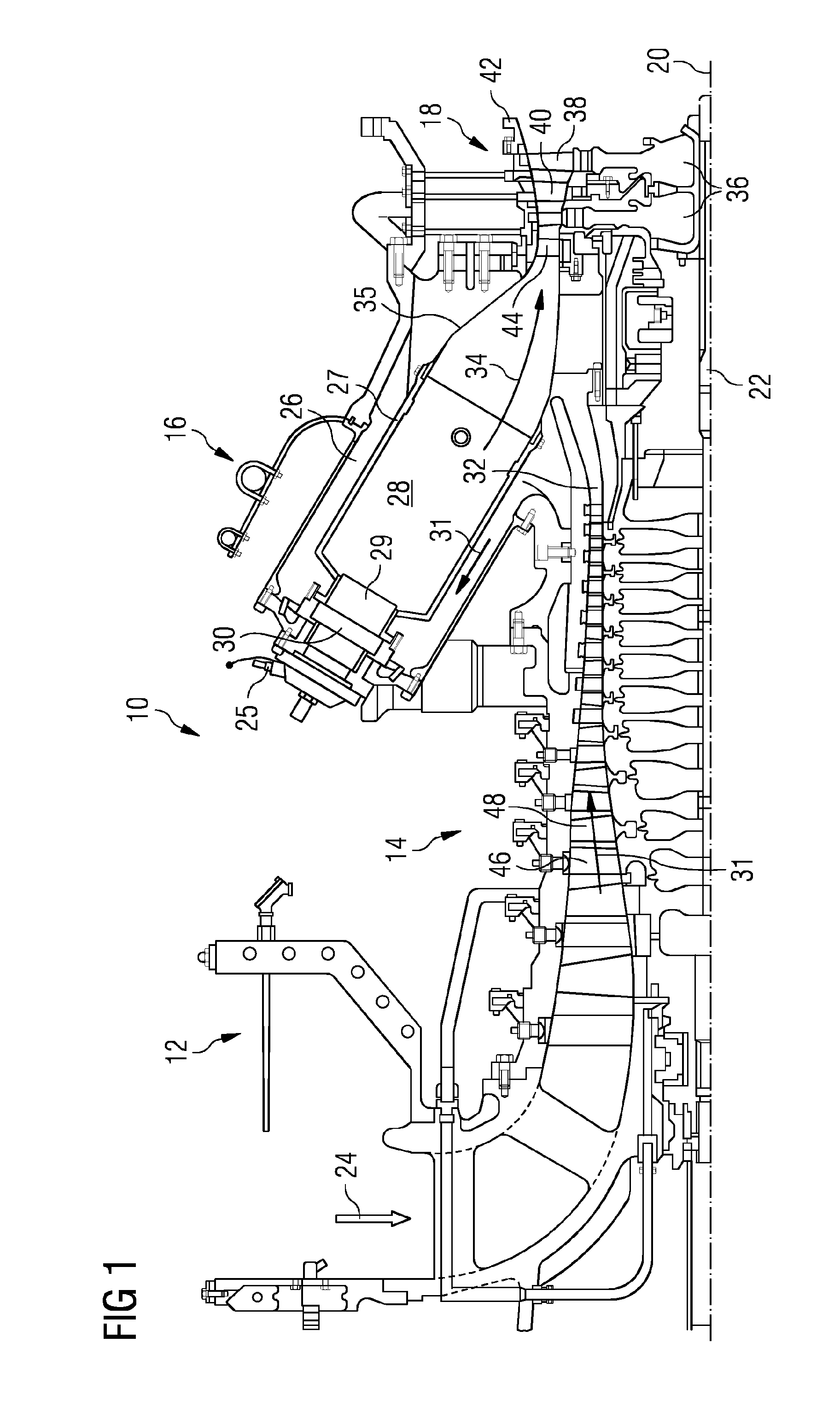
[0032]FIG. 1 shows an example of a gas turbine engine 10 in a sectional view and generally arranged about a longitudinal axis 20. The gas turbine engine 10 comprises, in flow series, an inlet 12, a compressor section 14, a combustor section 16 and a turbine section 18 which are generally arranged in flow series and generally in the direction of the longitudinal or rotational axis 20. The gas turbine engine 10 further comprises a shaft 22 which is rotatable about the rotational axis 20 and which extends longitudinally through the gas turbine engine 10. The shaft 22 drivingly connects the turbine section 18 to the compressor section 12. The combustor section 16 comprises an annular array of combustor units 16 only one of which is shown.

[0033]In operation of the gas turbine engine 10, air 24, which is taken in through the air inlet 12 is compressed by the compressor section 14 and delivered to the combustion section or unit 16. The combustor unit 16 comprises a burner plenum 26, a pre-...


PUM


Abstract

A fuel lance for a burner of a combustor has a fuel lance body defining a fuel flow passage and a liquid fuel tip attached thereto and in flow communication with fuel flow passage. The liquid fuel tip has a fuel outlet and an array of air passages having outlets which are arranged outside a blank sector of a circumference around the fuel outlet, the blank sector defined by an angle from 30° to 160°. A burner includes the fuel lance and the igniter and a main air flow passage to direct at least a part of a main air flow over the fuel lance and over the igniter, the blank sector has a centre-line angled between +120° and −120° from a radial line from the axis and passing through the fuel lance. A method includes rotating the fuel lance between a start-up condition and a second condition.

Description

CROSS REFERENCE TO RELATED APPLICATIONS[0001]This application is the US National Stage of International Application No. PCT / EP2015 / 059444 filed Apr. 30, 2015, and claims the benefit thereof. The International Application claims the benefit of European Application No. EP14166841 filed May 2, 2014. All of the applications are incorporated by reference herein in their entirety.FIELD OF INVENTION[0002]The present invention relates to combustion equipment of a gas turbine engine and in particular a liquid fuel lance for a burner arrangement of the combustion equipment, the burner arrangement and a method of operating the combustor equipment.BACKGROUND OF INVENTION[0003]Gas turbines including dry low emission combustor systems can have difficulty lighting and performing over a full load range when using liquid fuels. Often this can be because of fuel placement and subsequent atomization of the fuel in mixing air flows particularly at low loads. Ideally, the fuel droplets need to be very s...

Claims


Application Information

Patent Timeline
Patent Type & Authority Applications(United States)
IPC IPC(8): F23R3/38F23R3/12F02C7/264F23R3/28
CPCF23R3/38F23R3/286F05D2220/32F02C7/264F23R3/12F23D11/12F23R3/04F23R3/14F23R2900/00004
Inventor STEVENSON, IMOGENBICKERTON, RONALDDOLMANSLEY, TIMOTHY
Owner SIEMENS ENERGY GLOBAL GMBH & CO KG
Why Eureka
Try Eureka