Optical fiber and method of manufacturing optical fiber
a technology of optical fiber and manufacturing method, applied in the field of optical fiber, can solve the problems of signal processing not fast enough, signal deterioration, signal deterioration, etc., and achieve the effect of reducing dmd reliably and sufficiently, concentrating power, and increasing the amount of mode coupling
- Summary
- Abstract
- Description
- Claims
- Application Information
AI Technical Summary
Benefits of technology
Problems solved by technology
Method used
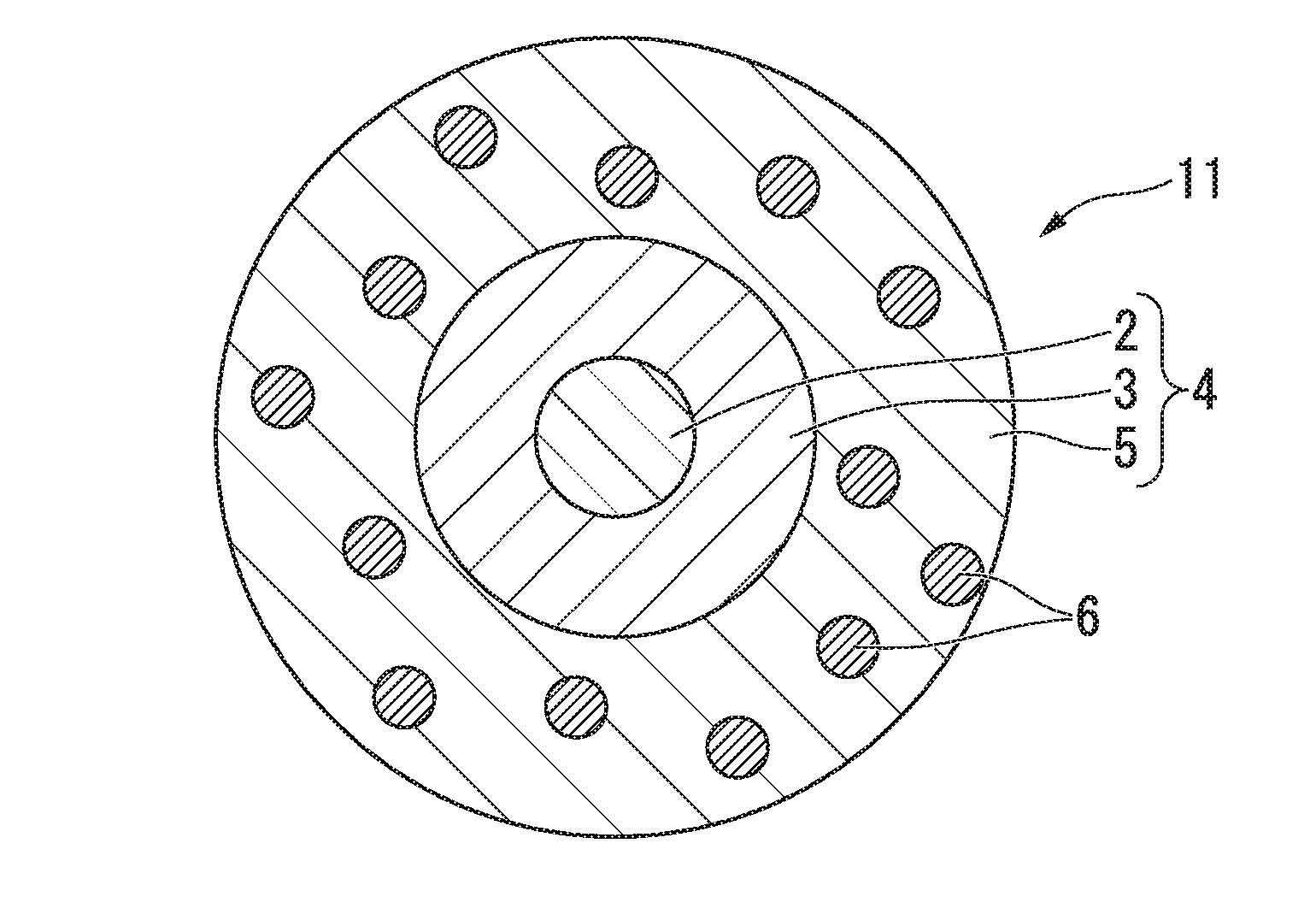
Image

Examples
example 1
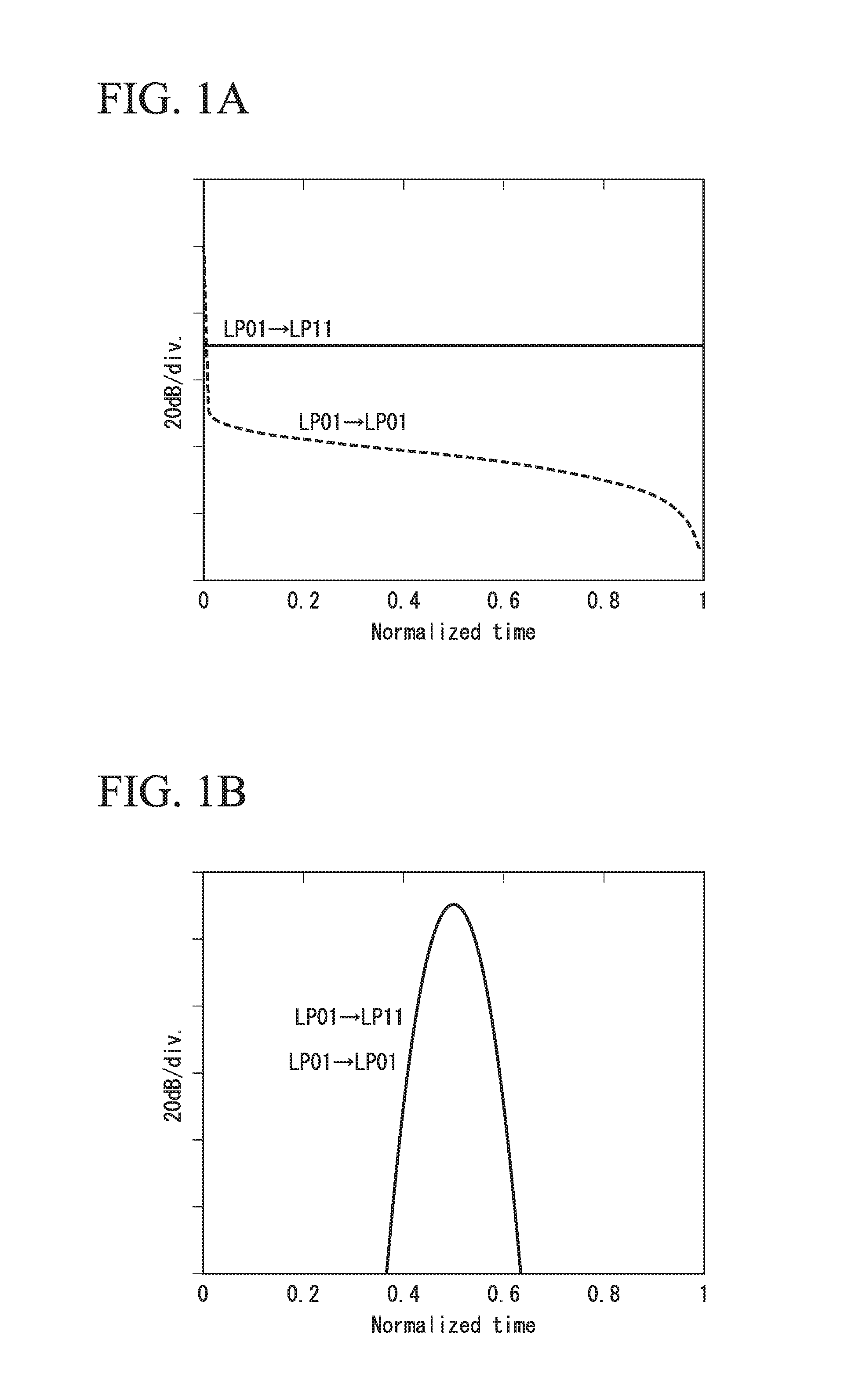
[0131]FIG. 5 shows a normalized impulse response waveform obtained in an optical fiber having the following characteristics.
[0132]h=2 [1 / km], the DMD τg=0.05 [ns / km], the transmission loss α1=α2=0.2 [dB / km], the optical fiber length z=100 [km], the velocity c of light in vacuum=2.998×10⁸ [m / s], the refractive index n0 of the core=1.45, and the amount XT of mode coupling=+23 [dB].
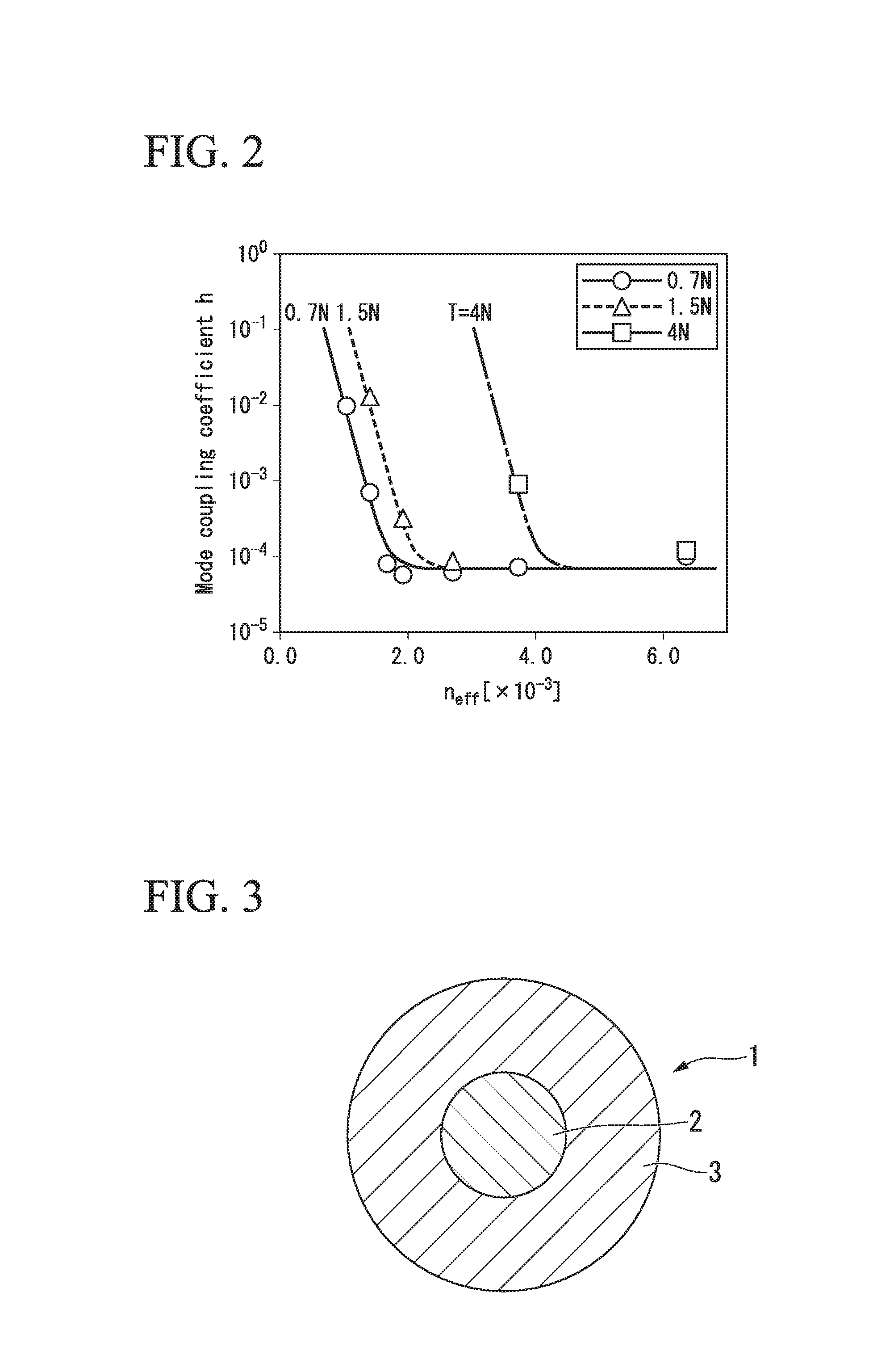
[0133]From the relationship between the mode coupling coefficient h and the effective refractive index difference Δneff shown in FIG. 2, Δneff for obtaining h=2 [1 / km] is 3.4×10⁻⁴.
example 2
[0138]FIG. 6 shows a normalized impulse response waveform obtained in an optical fiber having the following characteristics.
[0139]h=1×10⁻² [1 / km], the DMD τg=0.1 [ns / km], the optical fiber length z=10000 [km], and the amount XT of mode coupling=+20 [dB]. Other characteristics are the same as those in Example 1.
[0140]From the relationship between the mode coupling coefficient h and the effective refractive index difference Δneff shown in FIG. 2, Δneff for obtaining h=1×10⁻² [1 / km] is 1.0×10⁻³.
example 3
[0145]FIG. 7 shows a normalized impulse response waveform obtained in an optical fiber having the following characteristics.
[0146]h=3×10⁻² [1 / km], the DMD τg=0.2 [ns / km], the optical fiber length z=1000 [km], and the amount XT of mode coupling=+14.8 [dB]. Other characteristics are the same as those in Example 1.
[0147]From the relationship between the mode coupling coefficient h and the effective refractive index difference Δneff of FIG. 2, Δneff for obtaining h=3×10⁻² [1 / km] is 9.0×10⁻⁴.
PUM
| Property | Measurement | Unit |
|---|---|---|
| refractive index | aaaaa | aaaaa |
| length | aaaaa | aaaaa |
| plastic deformation | aaaaa | aaaaa |
Abstract
Description
Claims
Application Information