Neural Measurement

a neural activity and measurement technology, applied in the field of neural activity measurement, can solve the problems of difficult task, difficult cap measurement, and significant obstacle to isolating the cap of interest, and achieve the effect of improving the prevention of dc charge injection

Active Publication Date: 2017-02-23
SALUDA MEDICAL PTY LTD
View PDF2 Cites 74 Cited by
  • Summary
  • Abstract
  • Description
  • Claims
  • Application Information

AI Technical Summary

Benefits of technology

[0022]Some embodiments of the present invention further comprise a sense electrode capacitor provided in series between the sense electrode and the measurement amplifier, the sense electrode capacitor being chosen to have a capacitance which ensures that the voltage arising across the capacitor in response to the stimulus is constrained to a level which permits assessment of the neural response voltage seen at the sense electrode. Such embodiments may thus enable improved prevention of DC charge injection to the tissue, while nevertheless retaining neural response measurement capability. In such embodiments, the stimulus electrodes may have corresponding capacitors in order to prevent DC charge injection, and also to permit electrical reconfiguration of each electrode as either a stimulus electrode or sense electrode, as required.

Problems solved by technology

However, this can be a difficult task as an observed CAP signal will typically have a maximum amplitude in the range of microvolts, whereas a stimulus applied to evoke the CAP is typically several volts.
Electrode artefact usually results from the stimulus, and manifests as a decaying output of several millivolts throughout the time that the CAP occurs, presenting a significant obstacle to isolating the CAP of interest.
As the neural response can be contemporaneous with the stimulus and / or the stimulus artefact, CAP measurements present a difficult challenge of amplifier design.
In practice, many non-ideal aspects of a circuit lead to artefact, and as these mostly have a decaying exponential characteristic which can be of either positive or negative polarity, identification and elimination of sources of artefact can be laborious.
However, the provision of electrode capacitors or a star network of resistors between the electrodes and the measurement amplifier can give rise to considerable effects of artefact which can interfere with attempts to measure small CAP signals.

Method used


Image

  • Neural Measurement
  • Neural Measurement
  • Neural Measurement

Examples


Embodiment Construction

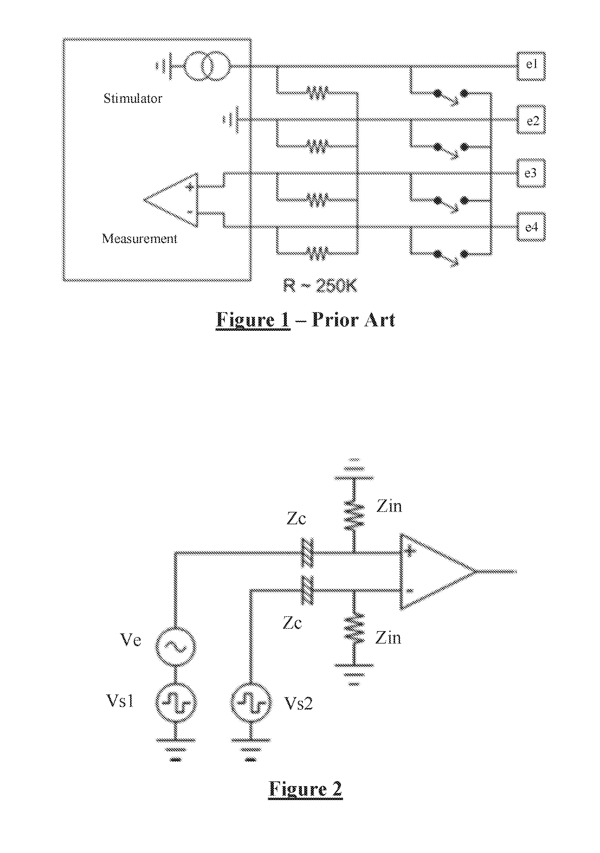
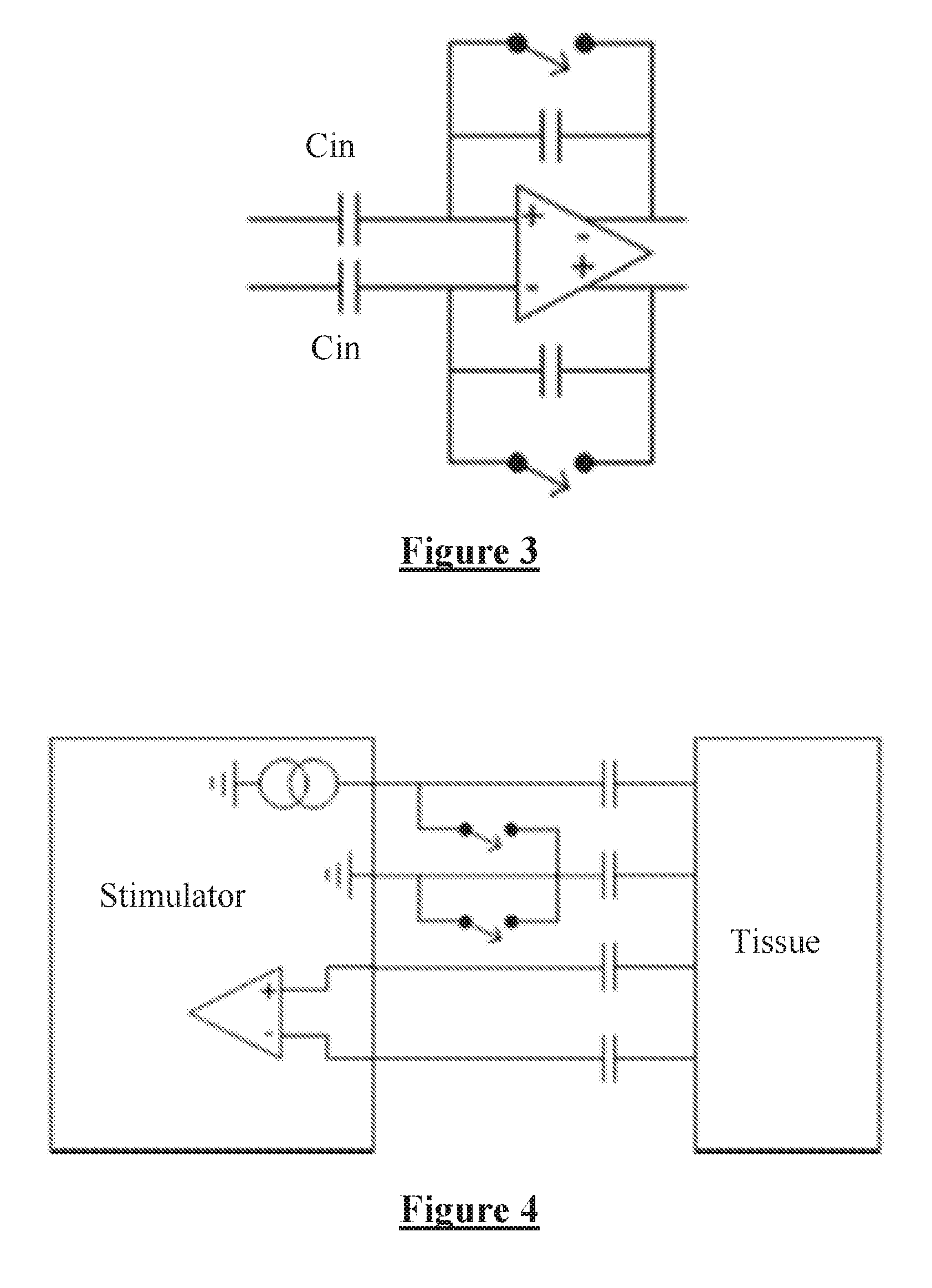
[0045]FIG. 2 illustrates a neural response measurement system in accordance with one embodiment of the present invention. Two sense electrodes each having a constant phase element (CPE) impedance of ZC are used to detect a neural response signal Ve arising in neural tissue of an implant recipient. A stimulus applied by stimulus electrodes of the implant (shown in FIG. 4) gives rise to the neural response, but also causes stimulus voltages Vs1 and Vs2 to be present on the sense electrodes. An input impedance of Zin is present at each input of the differential measurement amplifier.

[0046]The input impedance required in this embodiment of the invention is determined by noting that noise input is comparable to stimulation voltage, and that the goal is for the stimulus to induce a voltage (Vs1−Vs2) on the CPE of the sense electrodes which is less than the evoked response VE. Consequently the desired input impedance is given by:

ZIN>ZC(VS1-VS2)VE

[0047]In one embodiment, being a spinal cord...


PUM


Abstract

Measuring a neural response to a stimulus comprises applying an electrical stimulus, then imposing a delay during which the stimulus electrodes are open circuited. During the delay, a neural response signal present at sense electrodes is measured with a measurement amplifier, while ensuring that an impedance between the sense electrodes is sufficiently large that a voltage arising on the sense electrode tissue interface in response to the stimulus is constrained to a level which permits assessment of the neural response voltage seen at the sense electrode. For example the input impedance to the measurement amplifier (ZIN) can be
ZIN>ZC(VS1-VS2)VE,
where ZC is the sense electrode(s) constant phase element impedance, Vs1−Vs2 is the differential voltage arising on the sense electrode tissue interface, and VE is the neural response voltage seen at the sense electrode.

Description

CROSS-REFERENCE TO RELATED APPLICATIONS[0001]This application claims the benefit of Australian Provisional Patent Application No. 2014901639 filed 5 May 2014, which is incorporated herein by reference.TECHNICAL FIELD[0002]The present invention relates to measurement of neural activity, and in particular relates to measurement of a compound action potential or the like by using one or more electrodes implanted proximal to neural tissue.BACKGROUND OF THE INVENTION[0003]There are a range of circumstances in which it is desirable to obtain an electrical measurement of a compound action potential (CAP) evoked on a neural pathway by an electrical stimulus applied to the neural pathway. However, this can be a difficult task as an observed CAP signal will typically have a maximum amplitude in the range of microvolts, whereas a stimulus applied to evoke the CAP is typically several volts. Electrode artefact usually results from the stimulus, and manifests as a decaying output of several mill...

Claims


Application Information

Patent Timeline
Patent Type & Authority Applications(United States)
IPC IPC(8): A61B5/04A61N1/36A61N1/05
CPCA61B5/04001A61B5/04004A61N1/36135A61N1/0541A61N1/0551A61N1/0529A61N1/36128A61B5/30A61B5/24A61B5/7203A61B5/311
Inventor SINGLE, PETER SCOTT VALLACK
Owner SALUDA MEDICAL PTY LTD
Why Eureka
Try Eureka