Braking system for a draw works used for drilling operations

a technology of braking system and draw work, which is applied in the direction of mechanically actuated drum brakes, hydraulically actuated drum brakes, hoisting equipment, etc., can solve problems such as the rotation of the brake sha

Active Publication Date: 2017-02-23
NIELD BARRY J +1
View PDF22 Cites 6 Cited by
  • Summary
  • Abstract
  • Description
  • Claims
  • Application Information

AI Technical Summary

Problems solved by technology

Further, when the actuator lip is engaged against the shaft flange, movement of the piston rod may result in rotation of the brake shaft.

Method used


Image

  • Braking system for a draw works used for drilling operations
  • Braking system for a draw works used for drilling operations
  • Braking system for a draw works used for drilling operations

Examples


Embodiment Construction

[0016]Reference now will be made in detail to embodiments of the invention, one or more examples of which are illustrated in the drawings. Each example is provided by way of explanation of the invention, not limitation of the invention. In fact, it will be apparent to those skilled in the art that various modifications and variations can be made in the present invention without departing from the scope or spirit of the invention. For instance, features illustrated or described as part of one embodiment can be used with another embodiment to yield a still further embodiment. Thus, it is intended that the present invention covers such modifications and variations as come within the scope of the appended claims and their equivalents.

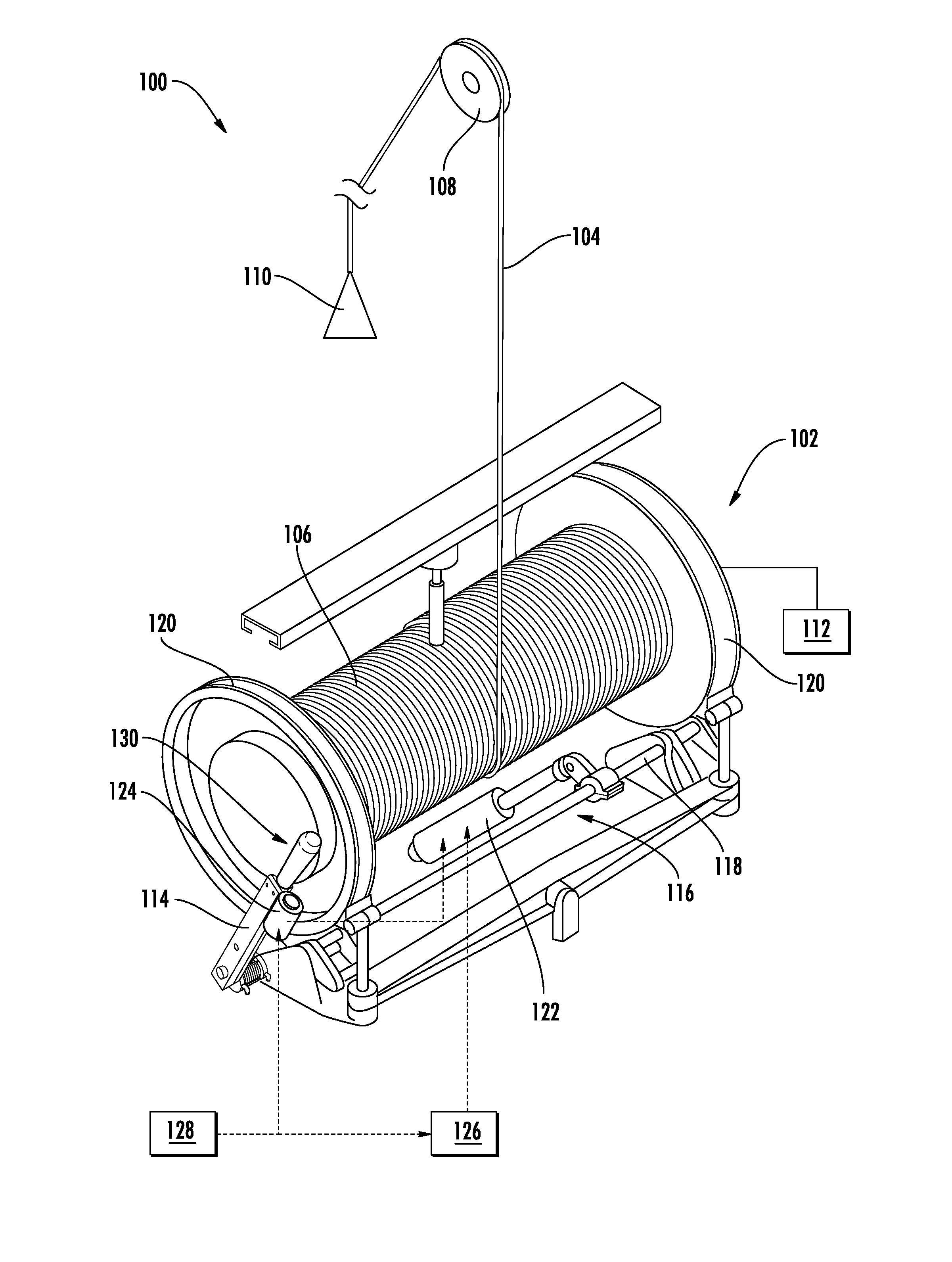
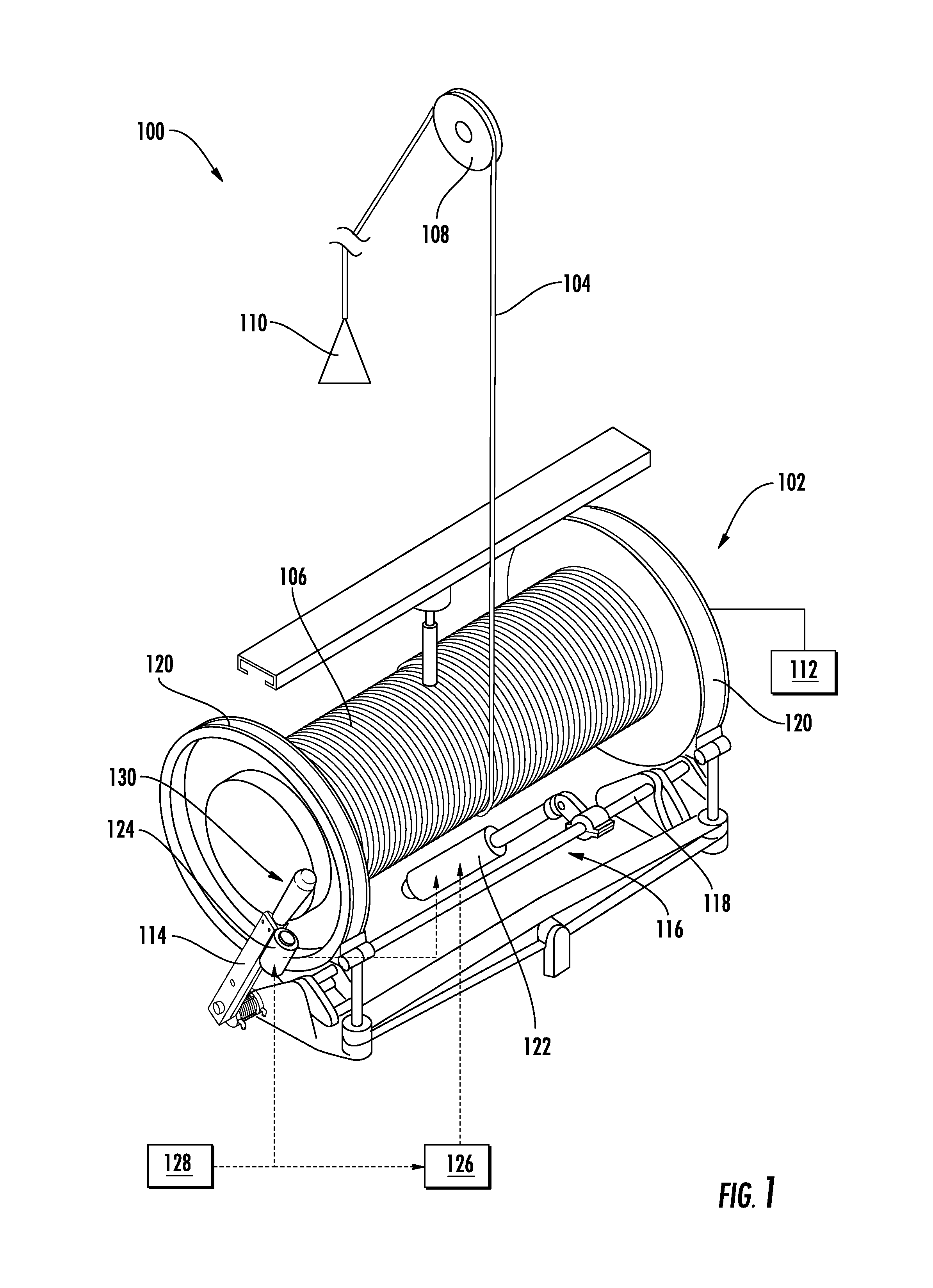
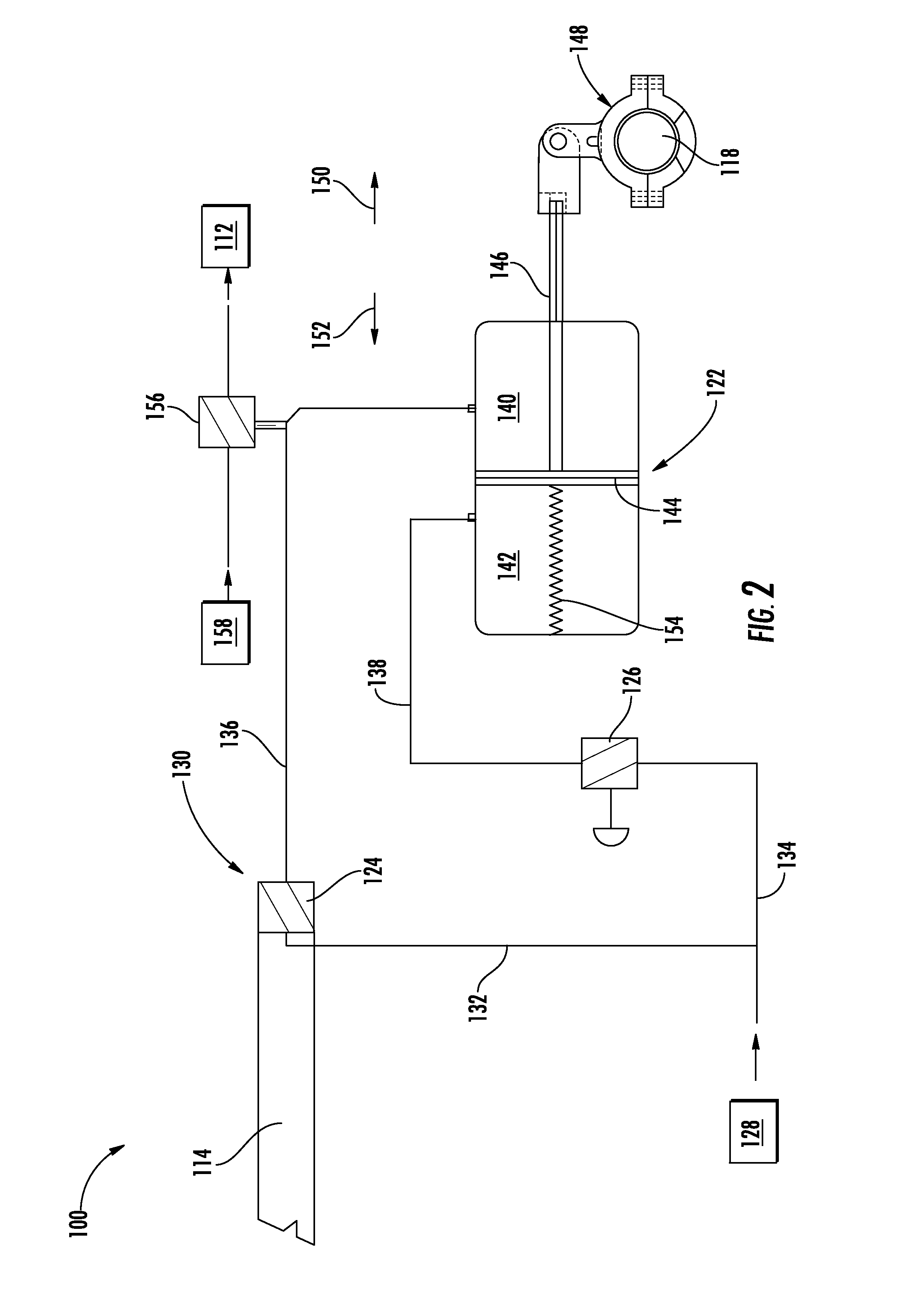
[0017]In general, the present subject matter is directed to an improved braking system for a draw works used in connection with a drilling rig for performing drilling operations. Specifically, in several embodiments, the braking system may include a handle / ...


PUM


Abstract

A braking system may include a brake assembly having a brake shaft and a brake lever coupled to the brake shaft. The system may also include a brake cylinder having a first chamber, a second chamber, a piston positioned between the chambers and a piston rod extending outwardly from the piston. The piston rod may be configured to be coupled to the brake shaft such that movement of the piston rod results in rotation of the brake shaft. In addition, the system may include a first valve configured to control a supply of working fluid to the first chamber and a second valve configured to control a supply of the working fluid to the second chamber. By adjusting a position of the first valve and / or the second valve, a braking force applied between the brake assembly and a drum of the draw works may be controlled.

Description

FIELD OF THE INVENTION[0001]The present subject matter relates generally to drilling rigs and, more particularly, to a braking system for a draw works or hoist used in connection with a drilling rig for performing drilling operations.BACKGROUND OF THE INVENTION[0002]Drilling rigs often include a machine known as a draw works or hoist for raising and lowering piping and drill bits. A typical draw works includes a drill line wound around a large drum or spool. The drill line extends from the drum through a pulley or other block and tackle arrangement to a travelling block. A, drive system rotates the drum to reel in the drill line and a brake lever may be manually operated to apply or release one or more component of a brake assembly connected to the drum. For example, the brake lever may be positioned to manually release the brake assembly to allow the drive system to rotate the drum to reel in the drill line and raise the travelling block. Alternately, the drive system may be discon...

Claims


Application Information

Patent Timeline
Patent Type & Authority Applications(United States)
IPC IPC(8): B66D5/26B66D5/08F16D49/00
CPCB66D5/26B66D5/08F16D49/00B66D5/10F16D49/10F16D49/12F16D2121/02F16D2121/14
Inventor NIELD, BARRY J.NIELD, G. ALEXANDER
Owner NIELD BARRY J
Why Eureka
Try Eureka