System and method for tomographic lifetime multiplexing

a lifetime multiplexing and lifetime technology, applied in the field of timedomain fluorescent tomography, can solve the problems of significant lifetime cross-talk, continuous wave (cw), and inability to provide the measurement of fluorescence or phosphorescence lifetimes, and achieve the effect of increasing the spatial resolution of optical detection

Active Publication Date: 2017-02-23
THE GENERAL HOSPITAL CORP
View PDF1 Cites 4 Cited by
  • Summary
  • Abstract
  • Description
  • Claims
  • Application Information

AI Technical Summary

Benefits of technology

[0006]An embodiment of the present invention provides a method for increasing spatial resolution of optical detection carried out with an optical tomography system Such embodiment includes detecting fluorescent light, emitted by at least one irradiated fluorophore that has been placed inside a turbid medium, to obtain, for at least one source-detector pair of the system and corresponding lifetimes of said at least one irradiated fluorophore a) a first one-dimensional (1D) optical data vector representing fluorescence temporal point spread functions (TPSFs) of said at least one irradiated fluorophore for a first number of early time-windows, and b) a second 1D optical data vector representing decay amplitudes of the at least one fluorophores for a ...

Problems solved by technology

Conventional tomography systems utilize continuous-wave (CW) methodology that is incapable to provide the measurement of fluorescence or phosphorescence lifetimes and does not utilize the low-scattering early-arriving photons.
While the recently developed time-resolved techniques provide several advantages when used in fluor...

Method used


Image

  • System and method for tomographic lifetime multiplexing
  • System and method for tomographic lifetime multiplexing
  • System and method for tomographic lifetime multiplexing

Examples


example 1

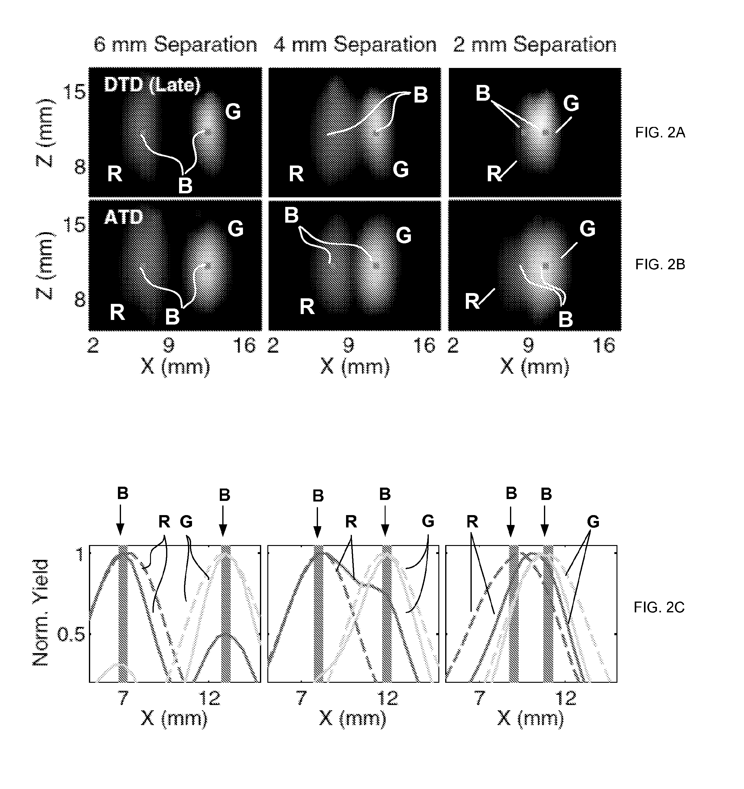
[0057]FIGS. 2A, 2B, 2C illustrate a comparison between the reconstructed fluorescent images procured with the use of the ATD and DTD methodologies that were applied to the same set of 12 late time-gates. The three XZ plots of each of FIGS. 3A, 3B correspond, respectively, to fluorophore-to-fluorophore separation of 6 mm, 4 mm, and 2 mm along the x-axis. FIG. 2C provides line plots for ATD (dashed line) and DTD (solid line) along the x-axis at the depth of the inclusion, obtained from the data of FIGS. 2A, 2B. The computation time for ATD was 21 times shorter than that for DTD. It can be seen from the line plots of FIG. 2C that there is significantly higher cross-talk for reconstructions obtaine d with the us e of the DTD than that in case of the ATD reconstruction. Such high-level of cross-talk in practice precludes accurate localization of the fluorophores with the use of the DTD method even for a 4 mm separation. The ATD approach, however, provides minimal cross-talk and facilitat...

example 2

[0058]FIGS. 3A, 3B, 3C show the comparison of the results of yield reconstructions obtained with the use of the using the DTD approach with four early time-gates and those obtained with the embodiment of the invention according to Eqs. (7), (8). Each of FIGS. 3A and 3B includes three X-Z plots corresponding, respectively, to separations of 6 mm, 4 mm, and 2 mm along the x-axis. FIG. 3C provides line plots for fluorescent yield distribution obtained—with the HTD embodiment of the invention (dashed line) and DTD (solid line) along the x-axis at the depth of the inclusion—from the data of FIGS. 3A, 3B.

[0059]From the early DTD data it can be observed that, while the individual yield distributions are smaller than the ATD-derived distributions of FIG. 2B, the cross-talk is significantly higher than that characterizing the ATD distributions for all separations. Therefore, localization of the fluorophores in reliance on the early DTD data only once again leads to inaccurate results. For co...

example 3

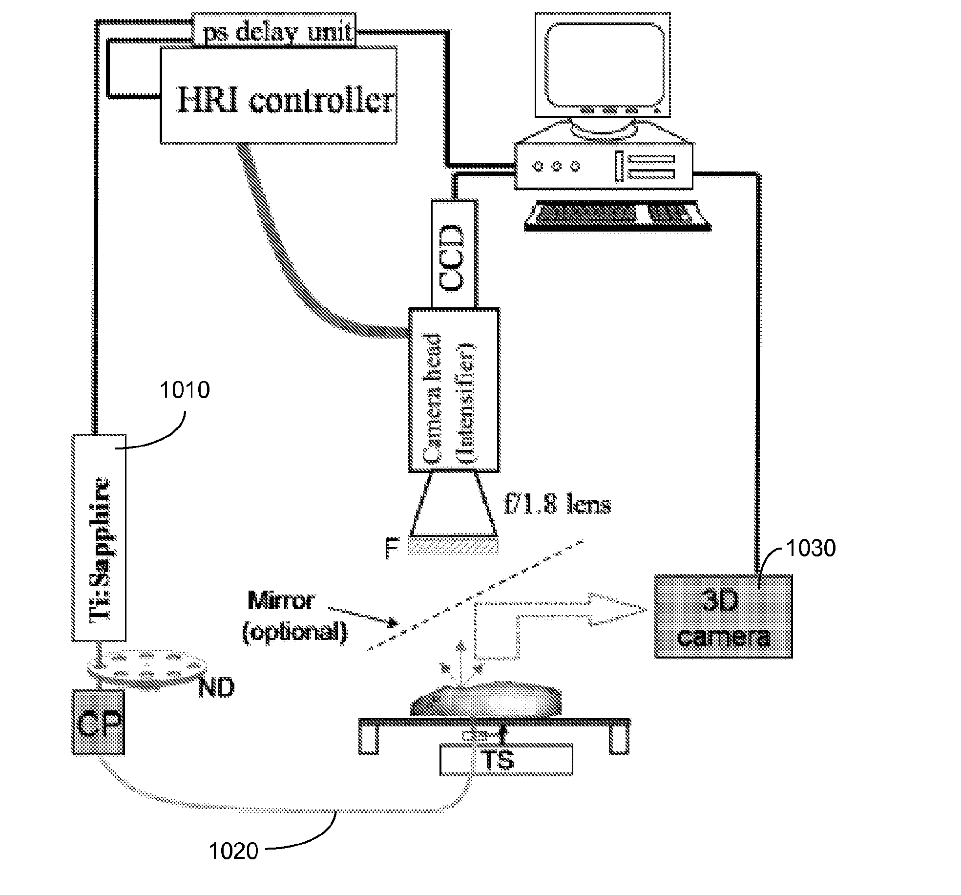
[0060]Additional independent validation of advantageous performance of the embodiment of the invention, phantom experiments were performed. To this end, parallel tubes filled with two dyes (τ1=0.87 ns and τ2=1.27 ns, respectively) and separated by 5.6, 2, and 1.4 mm, in three different scenarious, were embedded in a scattering medium consisting of intralipid and nigrosin (μa=0.1 cm1 and μ0s=10 cm1). Measurements were performed with a TD fluorescence tomography system that included a Ti-Sapphire laser for excitation and time-gated intensified CCD camera for detection. Full tomographic measurements were acquired for up to 84 sources and 84 detectors, and 46 time gates, with a time-gate width of 500 ps, CCD integration time of 100-200 ms, and the time-step size of 150 ps. The experimental reconstruction of fluorophores with life-time contrast in such phantom are illustrated in FIGS. 4A, 4B, 4C, 4D, and 4E.

[0061]Here, data-distributions marked R and G correspond to the yield-distributio...


PUM


Abstract

System and method for optical tomographic imaging optimizing analysis of time-domain data as a result of combination of lifetime multiplexing of low-cross-talk asymptotic photons with highly spatially resolved early photons. The tomographic data reconstruction employs a decay amplitude-based asymptotic approach and a matrix equation with a weight matrix that includes two different portions respectively representing time domain sensitivity functions and continuous-tomography weight matrices. System may employ a lifetime fluorescent tomography imaging system.

Description

CROSS REFERENCE TO RELATED APPLICATIONS[0001]This application claims the benefit of U.S. Provisional Patent Application No. 61 / 939,941, filed on Feb. 14, 2014 and titled “Systems and Methods for Tomographic Lifetime Multiplexing”, the entire contents of which are incorporated by reference herein, for all purposes.STATEMENT REGARDING FEDERALLY SPONSORED RESEARCH OR DEVELOPMENT[0002]This invention was made with government support under Grants Numbers R01 EB015325 and R01 EB000768 awarded by the National Institute of Health. The U.S. government has certain rights in the invention.TECHNICAL FIELD[0003]The present invention relates to time-domain fluorescent tomography and, in particular, to a method and system optimized for acquisition and analysis of time-domain fluorescent tomographic images that efficiently combine lifetime multiplexing using low cross-talk late-arriving (or asymptotic) photons with the high spatial resolution capability of the early photon tomography.RELATED ART[000...

Claims


Application Information

Patent Timeline
IPC IPC(8): G01N21/64
CPCG01N2201/06113G01N21/6408
Inventor KUMAR, ANAND T.HOU, STEVEN S.
Owner THE GENERAL HOSPITAL CORP
Why Eureka
Try Eureka