
Dental Implant Surgery Organizer Case

a dental implant and organizer technology, applied in the field of dental implant surgery, can solve the problems of implant site, poor primary fixation, malpractice, etc., and achieve the effect of preventing accidental mis-placement of implants

Inactive Publication Date: 2017-03-02
KRASTEV PAVEL
View PDF5 Cites 14 Cited by
  • Summary
  • Abstract
  • Description
  • Claims
  • Application Information

AI Technical Summary

Benefits of technology

This patent describes a dental implant case that has multiple compartments to hold various implant platform vials, which can be accessed easily by the surgeon during a surgery. The case can be positioned on a cart and extended for the surgeon's use. The lids of the compartments are unlatched to show which platform the surgeon needs for each tooth. This helps prevent accidental mis-placement of the implant and provides a visual cue to the surgeon.

Problems solved by technology

The significant drawbacks to the wearing of such partial or complete dentures, principally its means of support, which often required the use of adhesives, as well as its cleaning requirements served to bolster the development of dental implants.
Variations from a “recommended” platform size are frequently necessary, especially if a “spinner” occurs, which is an implant that does not have good primary fixation.
Therefore, the number of different sized / shaped platforms that the oral surgeon may need to have readily available during a procedure, to accommodate all of the implant sites, may often become considerable and unwieldy.
Where the patient requires multiple platforms to be implanted, and with the probability of needing to vary the platform selected for implantation from the “recommended” platform size, the potential for an error resulting in malpractice escalates.
Furthermore, increased handling of the vials that contain the platform in a sterile environment also introduces the likelihood of its mishandling, which may result in dropping of the vial and ruining of the sterile seal, which would necessitate the use of a new implant, at additional cost.

Method used


Image

  • Dental Implant Surgery Organizer Case
  • Dental Implant Surgery Organizer Case
  • Dental Implant Surgery Organizer Case

Examples


Embodiment Construction

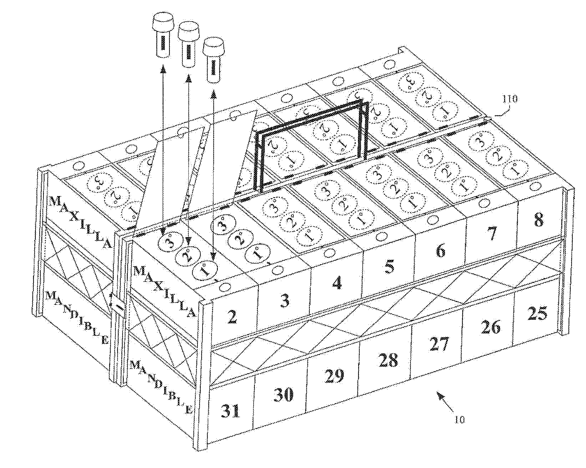
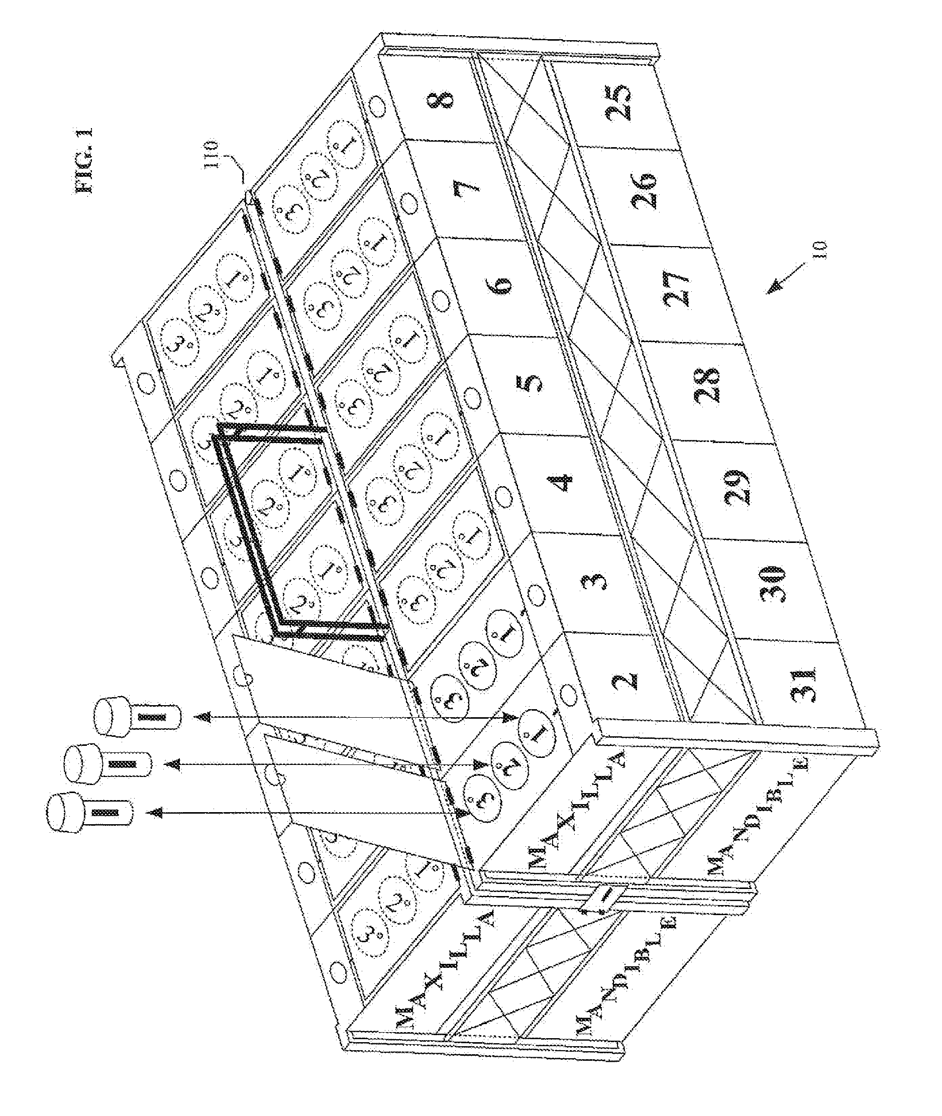
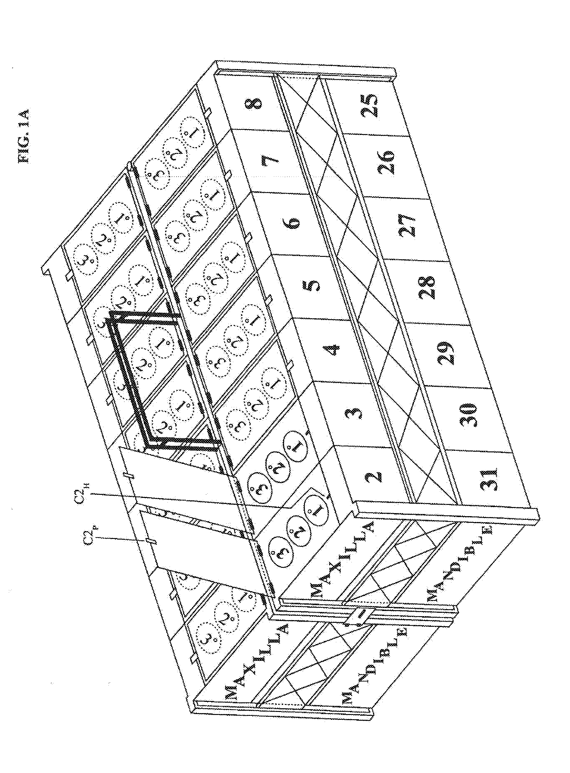
[0049]FIG. 1 shows a first embodiment of the dental implant organizer case 10 of the present invention, which serves to organize the multitude of implant platforms that may need to be readily available to an oral surgeon during the performance of implant procedures. As seen in FIG. 2, the dental implant organizer case 10 may comprise an elongated left-side case portion 10L being pivotally and / or releasably attached to an elongated right-side case portion 10R using hinge 110, where the left-side case portion and the right-side case portion may pivot 180 degrees relative to each other. Hinge 110, and its attachment to both the elongated left-side case 10L and the elongated right-side case 10R may permit the two cases to pivot between a collapsed position, in which they are parallel but side-by-side with each other (FIG. 1), and an extended position, in which they are parallel but in line with each other (FIG. 2). The left-side case 10L and the right-side case 10R may be releasably sec...


PUM


Abstract

A dental implant organizer case includes a housing with a plurality of compartments selectively arranged therein. Each compartment includes: a respective lid pivotally mounted to the housing to cover the compartment's cavity when closed; means for biasing the lid from the closed to the open position; means to releasably secure the lid in the closed position; means to releasably support dental implant containers within the compartment in an upright position; and a respective tooth number marking to indicate the tooth intended for the implant containers therein. The selectively arranged compartments may form a semi-circular or an in-line arrangement. Two compartment levels may be utilized, with the lower compartments being accessible using a tray being slidable with respect to the housing. Two cases may be secured together to be pivotable between collapsed and extended positions, where the first and second cases store dental implant containers for left-hand and right-hand teeth, respectively.

Description

CROSS REFERENCES TO RELATED APPLICATIONS[0001]This application claims priority on U.S. Provisional Application Ser. No. 61 / 692,789, filed on Aug. 24, 2012, the disclosures of which are incorporated herein by reference.FIELD OF THE INVENTION[0002]The present invention relates to improvements in dental implant surgery, and more particularly to apparatus which is adapted to aid an oral surgeon in organizing implants for a patient's procedure, and to help prevent dropping of implants, to help increase the speed of the procedure, and to reduce the likelihood of the surgeon inadvertently deviating from the intended procedure by eliminating confusion as to which implant belongs in a given site.BACKGROUND OF THE INVENTION[0003]There are many conditions which may result in a person becoming partially or completely edentulous (periodontal disease, an injury, etc.), which in the past had been remedied by the wearing of a prosthetic device, known as dentures. Dentures were constructed to replac...

Claims


Application Information

Patent Timeline
Patent Type & Authority Applications(United States)
IPC IPC(8): A61C19/10A61B50/33A61B90/94A61C19/02A61C8/00
CPCA61C19/10A61C19/02A61B2050/3015A61B90/94A61B50/33A61C8/0081A61C8/0087A61J1/03A61B50/20A61B50/31A61B2050/0056A61B2050/185A61B2050/3011A61B2050/311A61J1/00B65D21/0201
Inventor KRASTEV, PAVEL
Owner KRASTEV PAVEL
Learn More