Valve for tubeless tires

a valve and tubeless technology, applied in the field of valve stem systems, can solve the problems of reducing unclear how the amount of sealant in the inflated tire can be accurately determined and/or adjusted, etc., and achieves the effect of accurate measurement, easy and precise testing, and good results

Inactive Publication Date: 2017-03-02
SPORT COMPONENTS
View PDF10 Cites 6 Cited by
  • Summary
  • Abstract
  • Description
  • Claims
  • Application Information

AI Technical Summary

Benefits of technology

[0031]By furnishing the tubeless wheel with a valve stem system according to the present invention and applying the probe, the remaining amount of the sealant in the tire can be easily and precisely tested without releasing the air pressure or even removing the tire. The probe is made long enough to reach to the bottom of the tire through the valve stem body and the first valve element. The orifice should be arranged at a proper position in the tube wall, at least higher than the minimum sealant level in the tire, when the probe is inserted in the sealant and the second tube end reaches the bottom of the tire. Hence it can be determined if a tire contains a pre-defined minimum amount of sealant. Good results may be obtained if the orifice is arranged higher than the maximum sealant level as thus a wide range of possible sealant levels can be accurately measured.
[0032]A retaining element may be arranged at the first rod end and stops the moving of the second rod end in direction of the second tube end at the first rod position (p1). The retaining element serves on the one hand as a holding element to hold the rod, on the other hand as a stopper to limit the moving range of the rod in the tube.

Problems solved by technology

Due to dehydration, diffusion and leakage the amount of sealant usually decreases over time.
However it is still unclear how the amount of sealant in an inflated tire can accurately be determined and / or adjusted.

Method used


Image

  • Valve for tubeless tires
  • Valve for tubeless tires
  • Valve for tubeless tires

Examples


Embodiment Construction

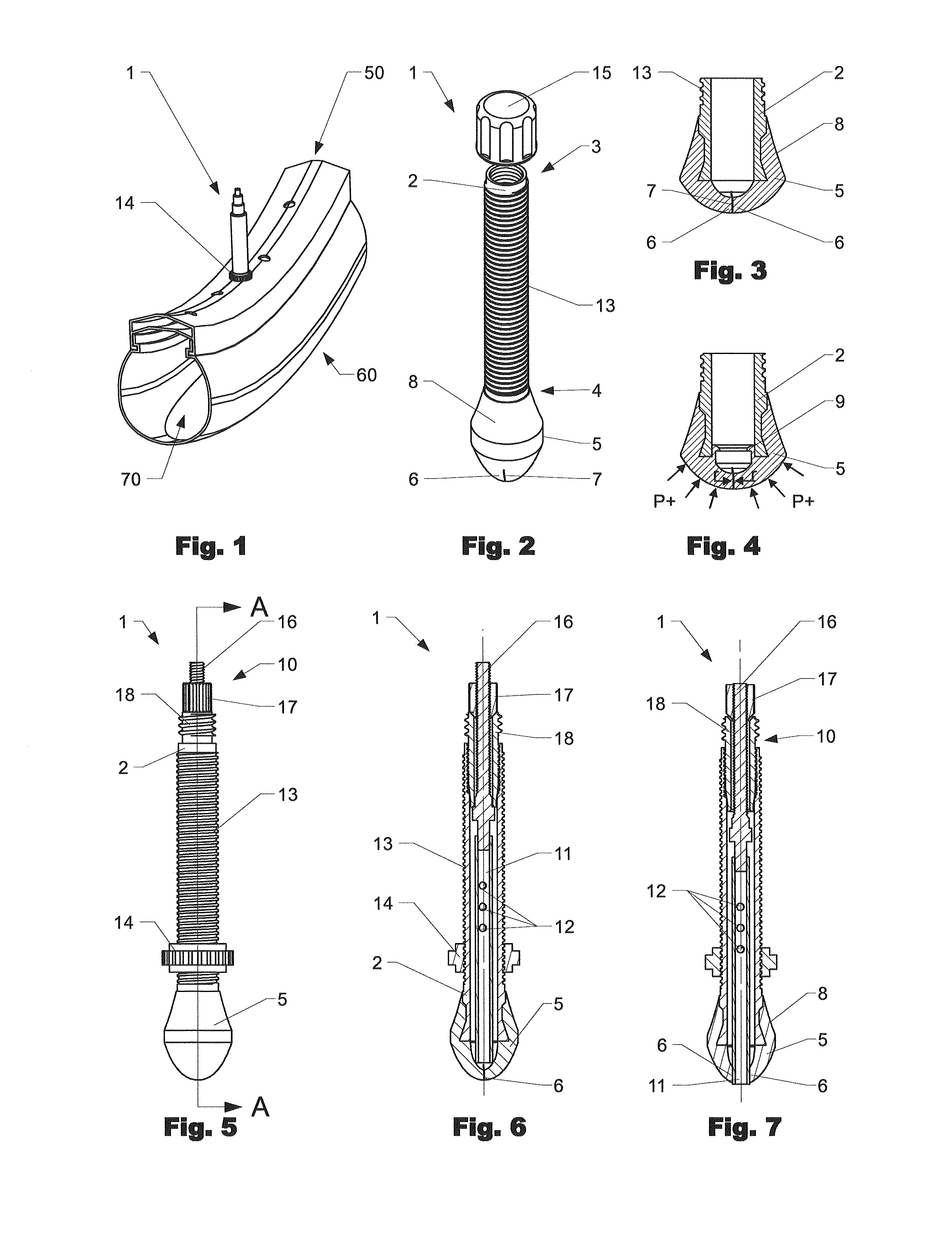
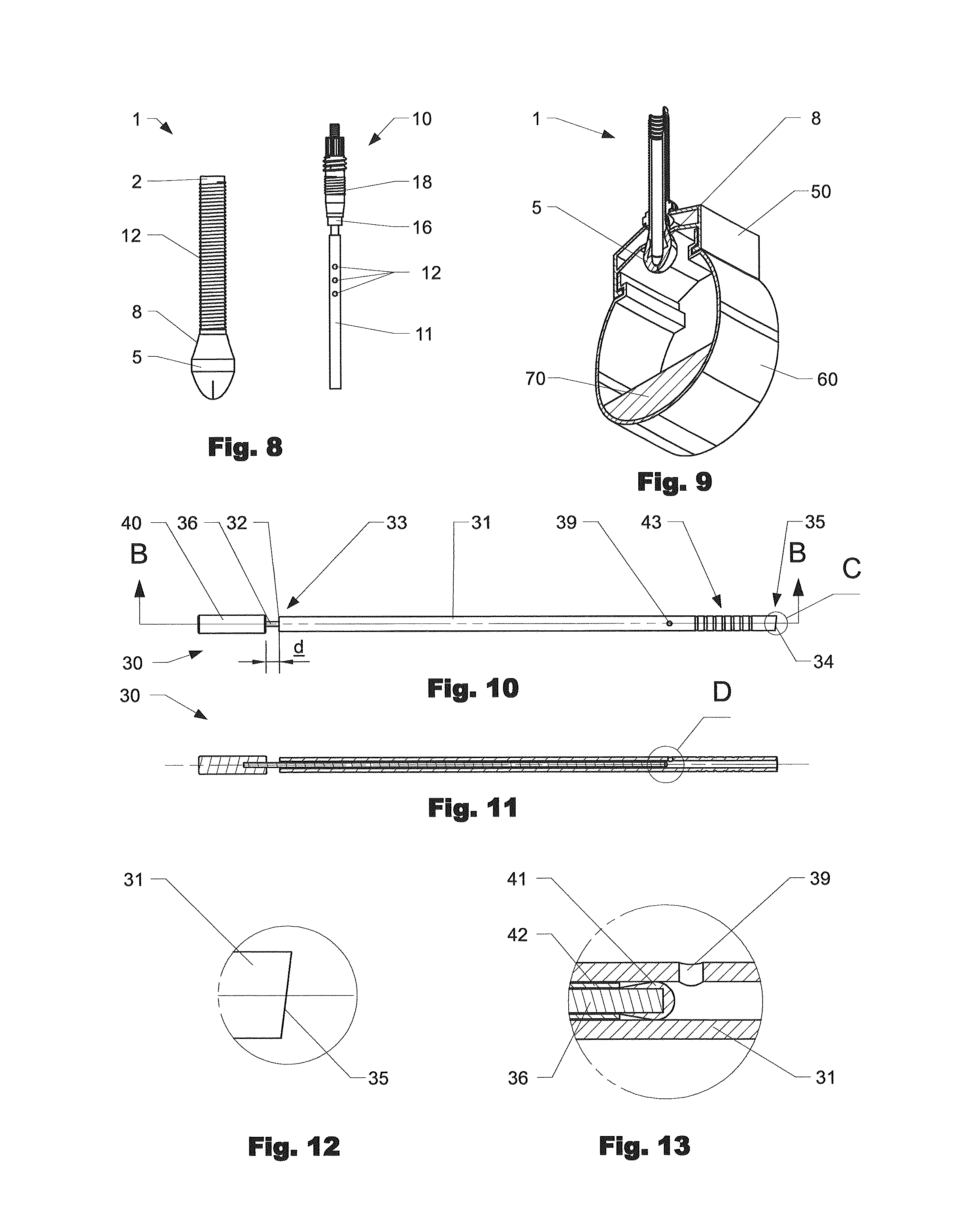
[0095]FIG. 1 shows an embodiment of a valve stem system 1 mounted on a wheel rim 50 including with a tire 60 mounted, in particular a tubeless wheel. The tire 60 is filled with sealant 70 for sealing the tire. The valve stem system 1 protrudes outward the outer (centripetal) surface of the rim and is fastened at the rim 50 using a nut 14.

[0096]FIG. 2 shows an embodiment of a valve stem system 1 comprising a tubular valve stem body 2 and a first valve element 5. The valve stem body 2 has a first end 3 and a second end 4 connected by a passageway which extends in longitudinal direction through the valve body 2. A cap 15, which can be threaded at the first end 3 of the valve stem body 2, is provided. The cap 15 protects the inner volume of the valve stem body 2 from pollution as well as it may serve as an additional sealing element to prevent the passage of pressurized gas through the valve stem body 2. The first valve element 5 is arranged at the second end 4 of the valve stem body 2,...


PUM

PropertyMeasurementUnit
volumeaaaaaaaaaa
elasticaaaaaaaaaa
diameteraaaaaaaaaa

Abstract

The invention is directed to a valve stem system (1) for tubeless wheels. The valve stem system (1) includes a valve stem body (2) with a first end (3) and a second end (4), wherein the second end (4) is located in a tire/rim-volume when mounted at the wheel. A first valve element (5) is arranged at the second end (4) of the valve stem body (2). The first valve element (5) is a self-sealing one-way valve. The invention further concerns a probe (30) for a valve stem system, a method to test the amount of sealant in a wheel and a refilling assembly (80) for a wheel.

Description

BACKGROUND OF THE INVENTION[0001]Field of the Invention[0002]The present invention is directed to a valve stem system e.g. for bicycle wheels, in particular for tubeless wheels.[0003]Discussion of Related Art[0004]WO 2010 / 009887 relates to a device for filling air tires, particularly bicycle tires, with a tire sealing fluid through the valves of the tires. The device is configured as an adapter set having a connector for the tire fluid, and having multiple individual parts which can be inserted into one another, and onto the valves by means of inserting, clipping, and / or screwing, which can be varied with respect to one another depending on the valve type, such as Dunlop valves, Quick valves, or Sclaverand valves.[0005]US 2006 / 0021472 relates to a device for injecting tire sealant fluid into a tire. A syringe type reservoir is connected to a long, flexible tube which is in turn connected to a valve stem connector. The valve stem connector has two different threads, Schrader and Pres...

Claims


Application Information

Patent Timeline
Patent Type & Authority Applications(United States)
IPC IPC(8): B60C29/06B60C5/12B60C29/00G01N33/26B60C25/05F16K15/20F16K15/14B60C5/00B60C25/00
CPCB60C29/062B60C5/004B60C5/12B60C29/005B60C25/005B60C2200/12B60C25/0551F16K15/202F16K15/147G01N33/26B60C25/0554B60C29/002
Inventor KOBLER, PIUSEGGERT, DOMINIK
Owner SPORT COMPONENTS
Why Eureka
Try Eureka