
Magnetic squeeze film damper system for a gas turbine engine

a gas turbine engine and magnetic squeeze film technology, which is applied in the direction of shock absorbers, machines/engines, liquid fuel engines, etc., can solve the problems of non-linear stiffness and damping coefficient achieved by typical sfds with respect to the orbital displacement of the shaft, and abnormal rotational unbalance of the high-pressure turbine sha

Active Publication Date: 2017-03-02
ROLLS ROYCE NORTH AMERICAN TECH
View PDF16 Cites 21 Cited by
  • Summary
  • Abstract
  • Description
  • Claims
  • Application Information

AI Technical Summary

Benefits of technology

The present disclosure is for a magnetic squeeze film damper system. The system includes a housing with a channel for flowing a fluid, which is bordered by the outer surface of a bearing. The system also includes two seal glands located at the ends of the channel, which are designed to seal the fluid and prevent it from leaking. The seal glands contain a reservoir containing a fluid with suspended metal particles, such as a magneto-rheological fluid. The system includes an electronic control system which generates current to activate the magnets. The technical effect of this patent is to provide a more efficient and effective magnetic squeeze film damper system for controlling the movement of objects.

Problems solved by technology

Moreover, rotating shafts in gas turbine engines can become abnormally unbalanced while operating.
For example, a high pressure turbine shaft can become abnormally unbalanced after a turbine blade failure.
However, both the stiffness and the damping coefficient achieved by typical SFDs are non-linear with respect to the orbital displacement of the shaft.
Because current SFD systems do not provide for variable control during operation, they are not able to precisely locate and control response to critical speeds, since stiffness and damping are varied along with whirl displacement.

Method used


Image

  • Magnetic squeeze film damper system for a gas turbine engine
  • Magnetic squeeze film damper system for a gas turbine engine
  • Magnetic squeeze film damper system for a gas turbine engine

Examples


Embodiment Construction

[0014]For the purposes of promoting an understanding of the principles of the disclosure, reference will now be made to the embodiments illustrated in the drawings and described in the following written specification. It is understood that no limitation to the scope of the disclosure is thereby intended. It is further understood that the present disclosure includes any alterations and modifications to the illustrated embodiments and includes further applications of the principles disclosed herein as would normally occur to one skilled in the art to which this disclosure pertains.

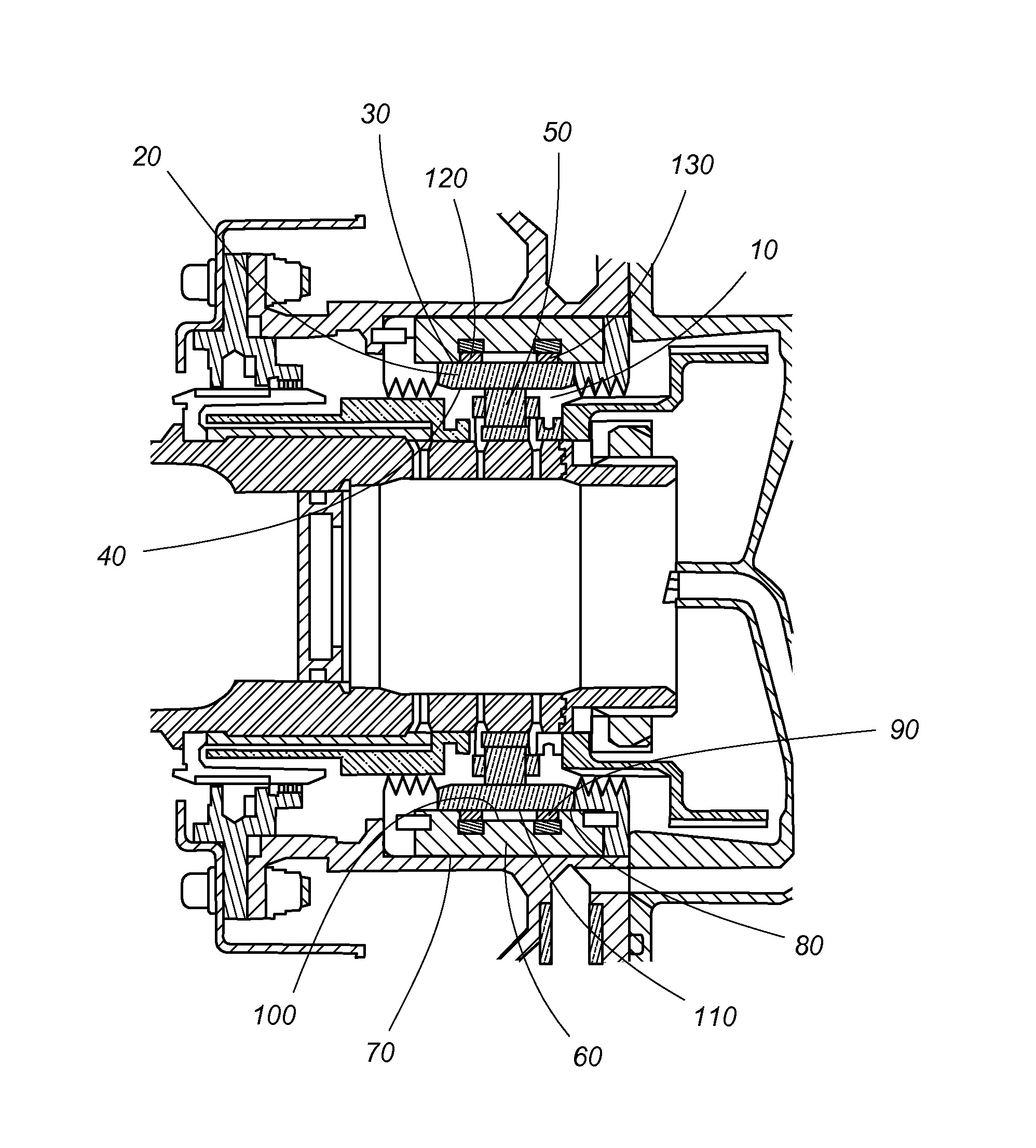
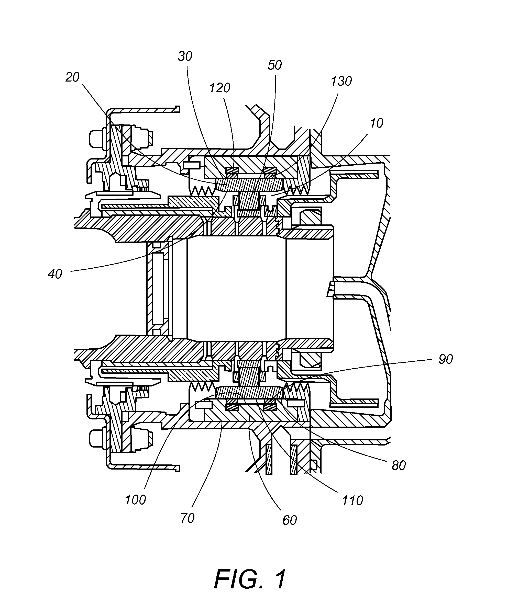
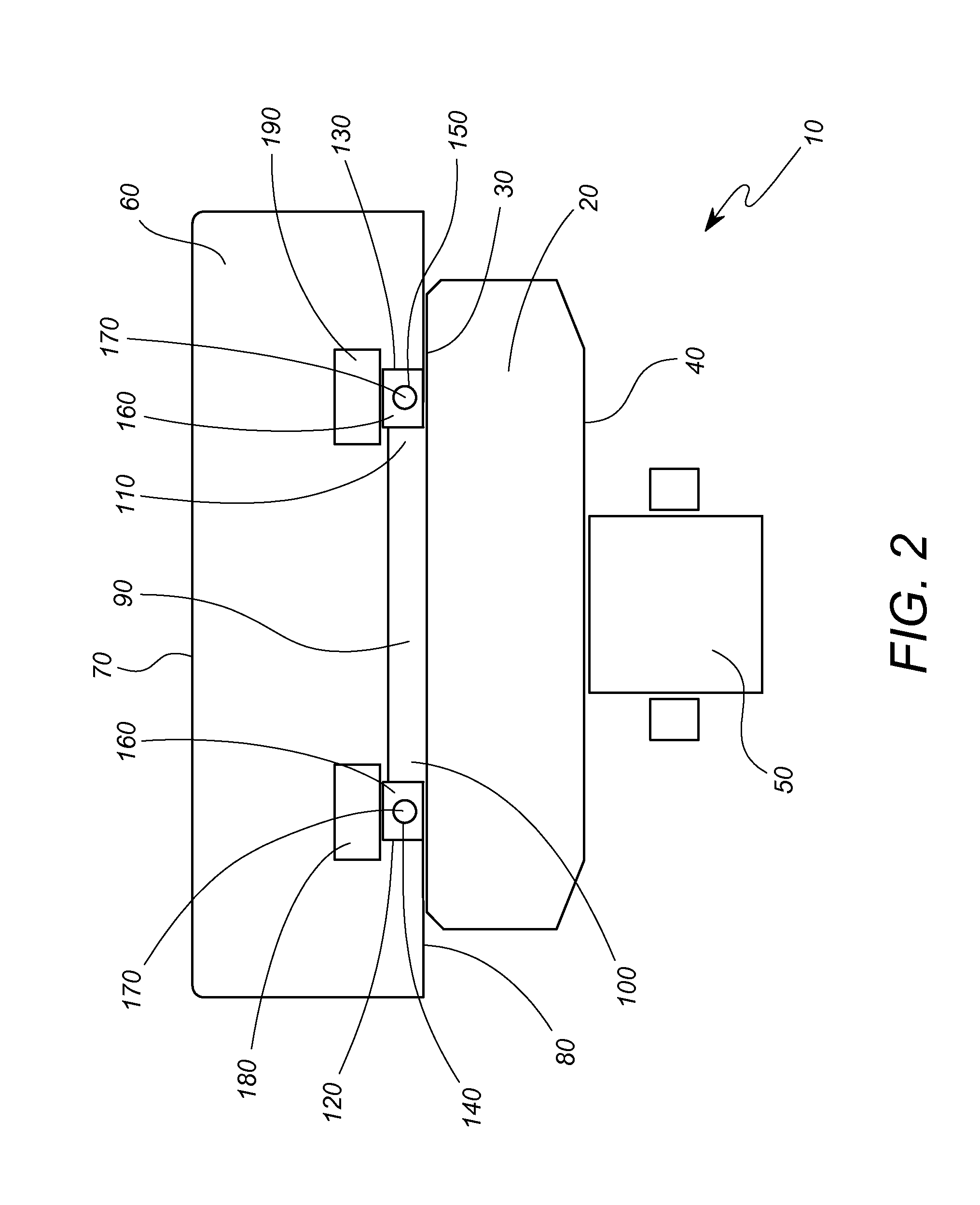
[0015]Referring to FIG. 1 and FIG. 2, a non-limiting embodiment of the present invention is depicted. One embodiment of the present invention includes a bearing assembly 10 having an outer race 20. The outer race 20 includes a first outer surface 30 and a first inner surface 40. The bearing assembly includes at least one bearing 50 located along the first inner surface 40. The at least one bearing can be any...


PUM


Abstract

A magnetic squeeze film damper system comprises a bearing assembly having an outer race with a first outer surface and a first inner surface and a bearing located along the first inner surface. The system further comprises a squeeze film damper housing having a second outer surface and a second inner surface that is contiguous with the first outer surface. A channel having a forward end and an aft end is defined within the housing along the second inner surface, the channel bordered by the first outer surface. The system further includes a first seal gland located along the forward end of the channel and a second seal gland located along the aft end of the channel. Both seal glands comprise a reservoir for holding a magneto-rheological fluid, the reservoir encased in an elastomer. At least one electromagnet is arranged in close proximity to each of the seal glands.

Description

BACKGROUND[0001]The present disclosure relates to devices and systems to address stability and vibration issues associated with high-speed rotating turbomachinery. More particularly, the present disclosure relates to devices and systems for addressing stability and vibration issues associated with gas turbine engines used in aircrafts, for example.[0002]In gas turbine engines, maintaining operational clearances between the tips of rotating blades and the engine static structure and controlling vibration generated by the high speed rotating components are design critical factors in gas turbine engine development. Maintaining operational clearances between the tips of rotating blades and the static structure of the engine to reduce air leakage past the rotating blades impacts the thermodynamic efficiency and specific fuel consumption (SFC) of the engine.[0003]Further, gas turbine engine shaft dynamics are critical, including the placement of shaft critical speed in the optimal frequen...

Claims


Application Information

Patent Timeline
Patent Type & Authority Applications(United States)
IPC IPC(8): F01D25/16F16F15/16F04D29/32F02C7/06F01D5/02F16C32/04F02C3/04
CPCF01D25/164F16C32/04F16F15/161F02C3/04F02C7/06F01D5/02F05D2260/96F16F2224/045F05D2220/32F05D2240/52F05D2240/54F05D2240/60F04D29/321F16C2360/23F16F15/0237F16C19/26F16C27/045F16C2210/06F05D2240/53F05D2300/507
Inventor COPELAND, ANDREW D.BURNS, DONALD W.CLEMENS, STANFORD O.COOKERLY, ALAN B.
Owner ROLLS ROYCE NORTH AMERICAN TECH
Learn More