Sound source identification apparatus and sound source identification method

Active Publication Date: 2017-03-02
HONDA MOTOR CO LTD
View PDF7 Cites 14 Cited by
  • Summary
  • Abstract
  • Description
  • Claims
  • Application Information

AI Technical Summary

Benefits of technology

[0018]According to the above-described aspects (1) and (7), it is possible to improve accuracy of the sound source identification since the identification of the sound source is performed using only the signal with a high SN ratio.
[0019]Further, in the case of the above-described aspects (2), (3), and (4), it is possible to prevent the sound source identification from being performed on noise since the sound source identification is performed only

Problems solved by technology

However, in the technology described in Patent Document 1, accuracy of sound source identification is affected by the quality of a signal input to

Method used


Image

  • Sound source identification apparatus and sound source identification method
  • Sound source identification apparatus and sound source identification method
  • Sound source identification apparatus and sound source identification method

Examples


first embodiment

1>

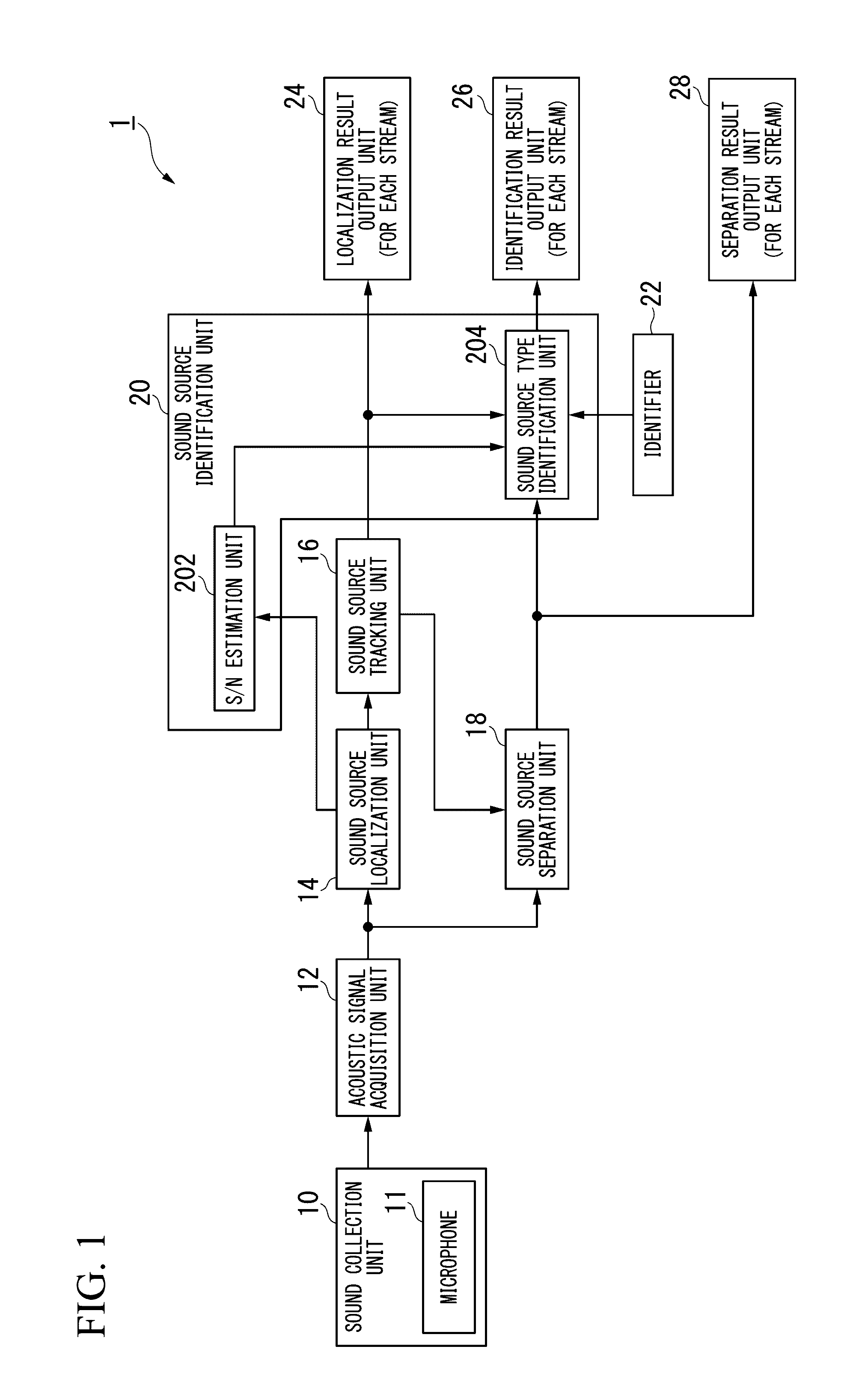
[0038]FIG. 1 is a block diagram illustrating a configuration of a sound source identification apparatus 1 according to this embodiment.

[0039]As illustrated in FIG. 1, the sound source identification apparatus 1 includes a sound collection unit 10, an acoustic signal acquisition unit 12, a sound source localization unit 14, a sound source tracking unit 16, a sound source separation unit 18, a sound source identification unit 20, an identifier 22, a localization result output unit 24, an identification result output unit 26, and a separation result output unit 28. Further, the sound source identification unit 20 includes an S / N estimation unit 202 and a sound source type identification unit 204.

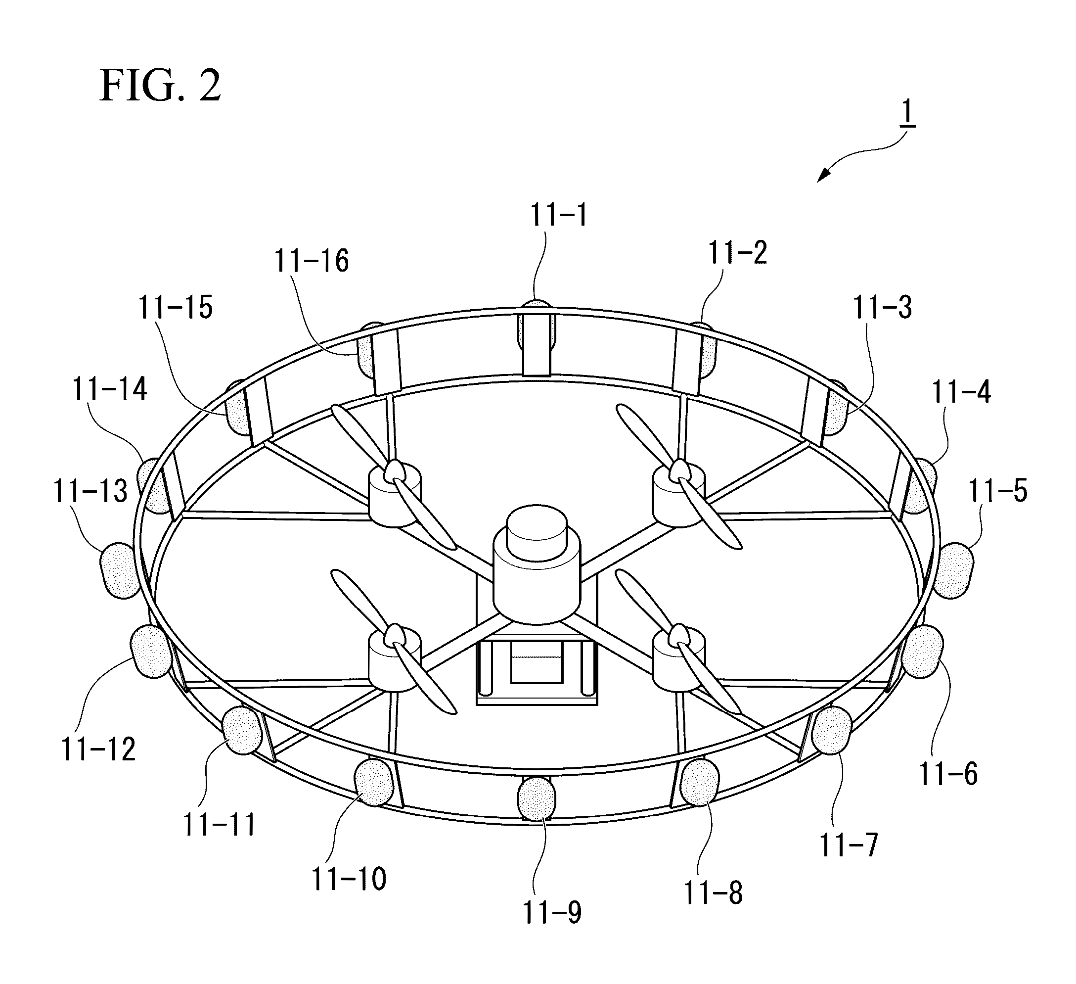
[0040]The sound collection unit 10 is a microphone array including M (M is an integer equal to or greater than 2) microphones 11. When no particular one of the plurality of microphones 11-1 to 11-M is specified, the microphones are referred to as a microphone 11. FIG. 2 is a diagram illustrat...

second embodiment

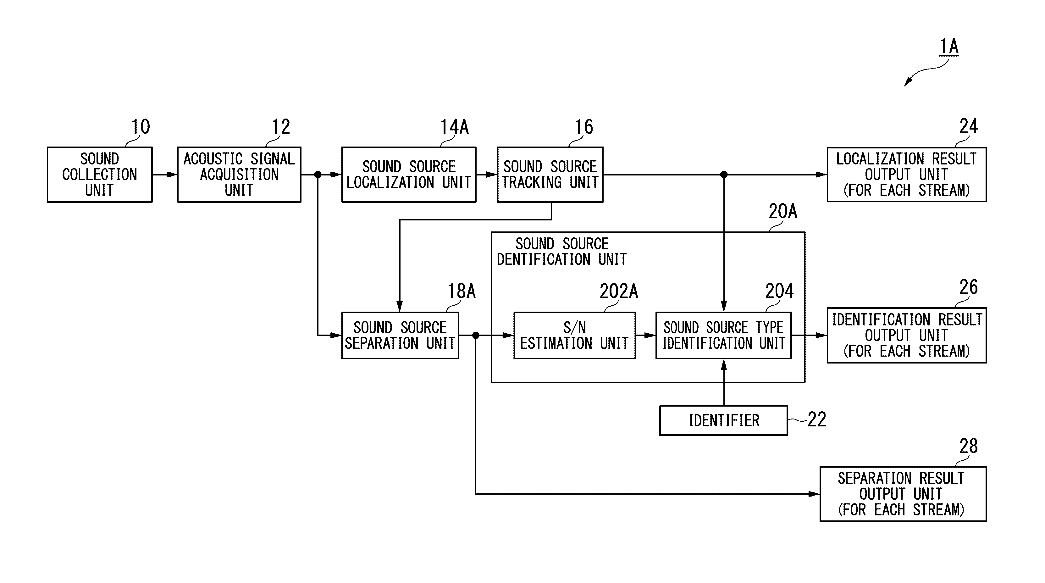
[0110]While the example in which the signal with a high SN ratio is extracted and the sound source identification is performed using the result of the sound source localization in the sound source localization unit 14 has been described in the first embodiment, in the second embodiment, an example in which the signal with a high SN ratio is extracted and the sound source identification is performed using a result of sound source separation in the sound source separation unit will be described.

1A>

[0111]FIG. 5 is a block diagram illustrating a configuration of a sound source identification apparatus 1A according to this embodiment.

[0112]As illustrated in FIG. 5, the sound source identification apparatus 1A includes a sound collection unit 10, an acoustic signal acquisition unit 12, a sound source localization unit 14A, a sound source tracking unit 16, a sound source separation unit 18A, a sound source identification unit 20A, an identifier 22, a localization result output unit 24, an ...

third embodiment

[0130]While the example in which the sound source separation unit 18A or the S / N estimation unit 202A compares the power of the spectrum with the second threshold value to detect the section in which there is an audio signal has been described in the second embodiment, in the third embodiment, an example in which the section in which there is an audio signal is detected with respect to an audio signal in a time domain and the sound source identification is performed will be described.

1B>

[0131]FIG. 7 is a block diagram illustrating a configuration of a sound source identification apparatus 1B according to a modification example of the embodiment.

[0132]As illustrated in FIG. 7, the sound source identification apparatus 1B includes a sound collection unit 10, an acoustic signal acquisition unit 12, a sound source localization unit 14A, a sound source tracking unit 16, a sound source separation unit 18B, a sound source identification unit 20B, an identifier 22, a localization result out...


PUM


Abstract

A sound source identification apparatus includes a sound collection unit including a plurality of microphones, a sound source localization unit configured to localize a sound source on the basis of an acoustic signal collected by the sound collection unit, a sound source separation unit configured to perform separation of the sound source on the basis of the signal localized by the sound source localization unit, and a sound source identification unit configured to perform identification of a type of sound source on the basis of a result of the separation in the sound source separation unit, and a signal input to the sound source identification unit is a signal having a magnitude equal to or greater than a first threshold value which is a predetermined value.

Description

CROSS-REFERENCE TO RELATED APPLICATION[0001]Priority is claimed on Japanese Patent Application No. 2015-168108, filed Aug. 27, 2015, the content of which is incorporated herein by reference.BACKGROUND OF THE INVENTION[0002]Field of the Invention[0003]The present invention relates to a sound source identification apparatus and a sound source identification method.[0004]Description of Related Art[0005]In acoustic signal processing, schemes such as sound source localization for identifying a sound source direction, sound source separation for separating a desired sound from a plurality of sounds, and sound source recognition (sound source identification) for specifying a type of sound source are used.[0006]Japanese Unexamined Patent Publication No. 2008-85472 (hereinafter, Patent Document 1) discloses a sound source identification apparatus including a sound source localization unit and a sound source identification unit, in which each of the sound source localization unit and the soun...

Claims


Application Information

Patent Timeline
IPC IPC(8): G10L21/028G10L25/84G10L25/30
CPCG10L21/028G10L25/84G10L25/30G10L2025/786G01S3/8006
Inventor NAKADAI, KAZUHIROUEMURA, SATOSHI
Owner HONDA MOTOR CO LTD
Why Eureka
Try Eureka