Armature, field element, method of manufacturing armature, method of manufacturing field element, and electrically powered machine

a field element and armature technology, applied in the direction of magnetic circuits, magnetic circuits characterised by magnetic materials, magnetic circuit shapes/forms/constructions, etc., can solve the problems of difficult deformation of dust cores, and low mechanical strength of dust cores. achieve high efficiency

Active Publication Date: 2017-03-02
SEIKO EPSON CORP
View PDF2 Cites 10 Cited by
  • Summary
  • Abstract
  • Description
  • Claims
  • Application Information

AI Technical Summary

Benefits of technology

[0010]An advantage of some aspects of the invention is to provide an armature and a field element, which can realize an electrically powered machine having high efficiency, an armature manufacturing method capable of manufacturing the armature, a field element manufacturing method capable of manufacturing the field element, and an electrically powered machine having high efficiency.

Problems solved by technology

However, the dust core has low mechanical strength, and therefore, when the coil is wound, there is a concern that the dust core may be chipped or broken.
With this configuration, it is difficult for deformation to occur, and at the time of forming, forming with a large compressive force becomes possible.
With this configuration, it becomes possible to fill an area between the conducting wires of the winding section with magnetic powder, and therefore, it becomes difficult for a gap to be formed between the coil and the dust core, and thus passage of a magnetic flux becomes easy.

Method used


Image

  • Armature, field element, method of manufacturing armature, method of manufacturing field element, and electrically powered machine
  • Armature, field element, method of manufacturing armature, method of manufacturing field element, and electrically powered machine
  • Armature, field element, method of manufacturing armature, method of manufacturing field element, and electrically powered machine

Examples


first embodiment

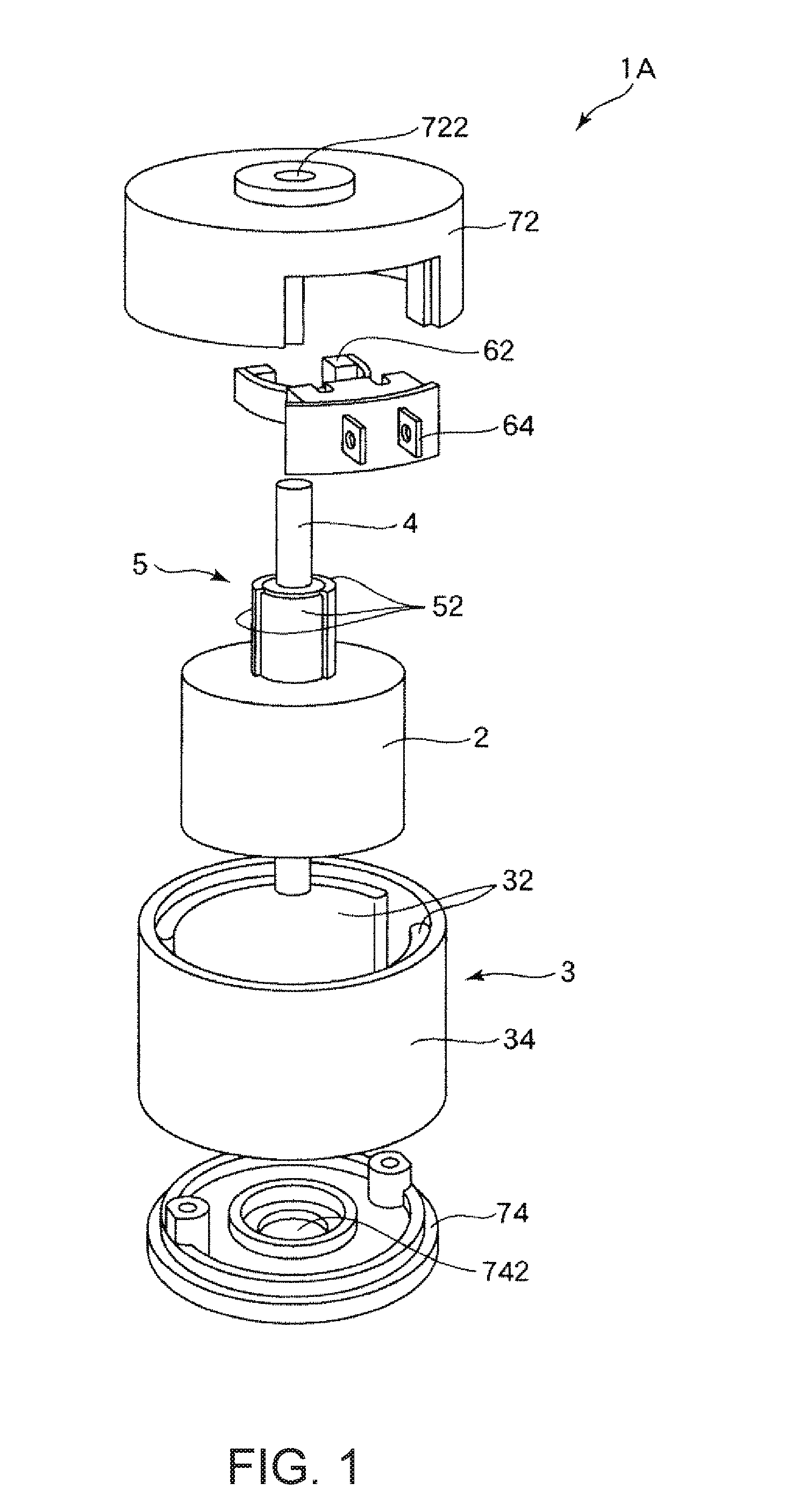
[0045]First, a first embodiment of an electrically powered machine according to the invention will be described. In addition, in this specification, an “electrically powered machine” refers to an electric motor (a motor), a power generator (a generator), or an electric motor-generator (a motor-generator) having the functions of both the electric motor and the power generator.

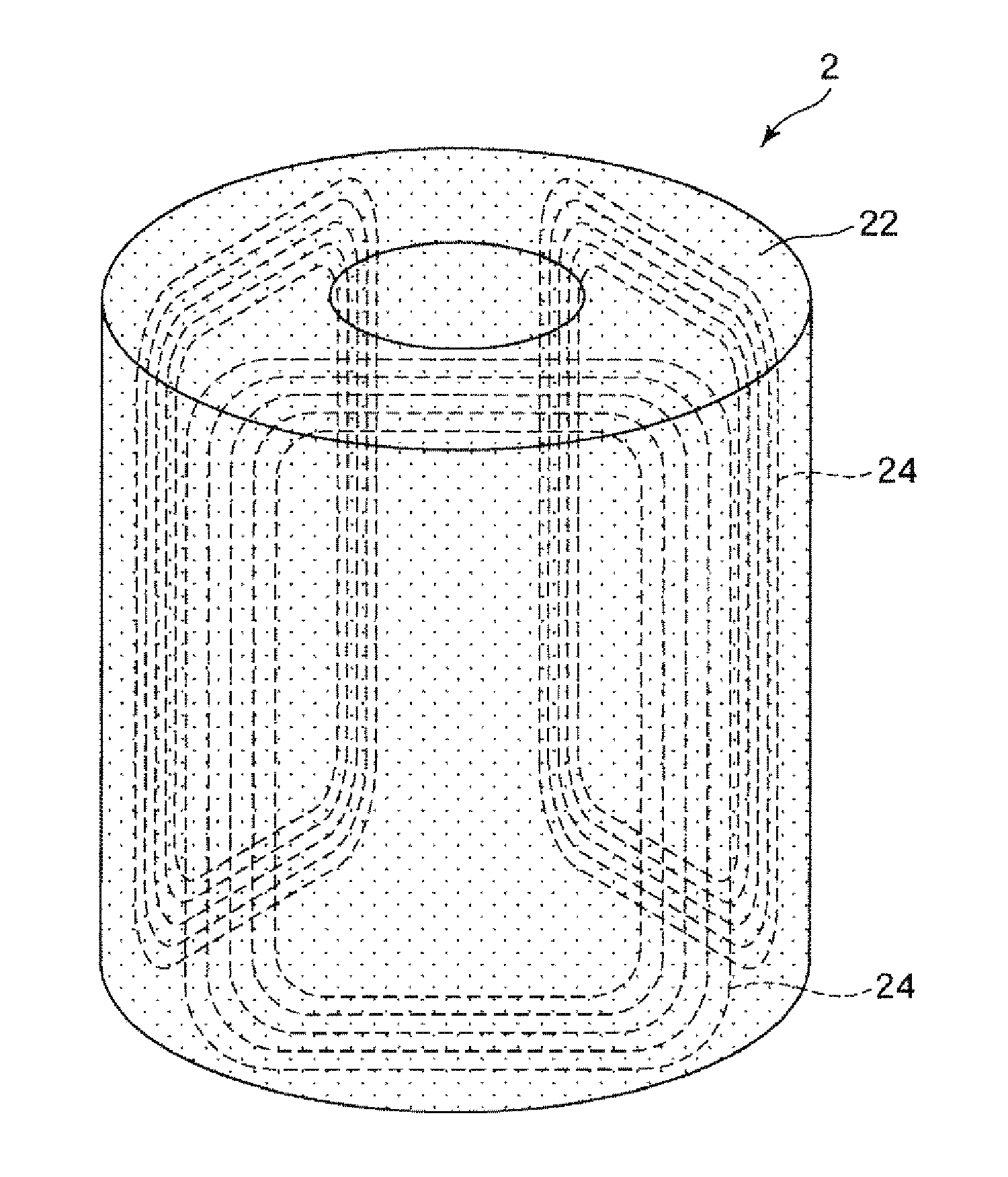
[0046]FIG. 1 is an exploded perspective view showing a direct-current electric motor (a DC motor) to which the first embodiment of the electrically powered machine according to the invention is applied. Further, FIG. 2 is a transparent perspective view showing an armature of the direct-current electric motor shown in FIG. 1, and FIG. 3 is a plan view when the armature shown in FIG. 2 is viewed from an extended line of a rotary shaft, and is a diagram showing such an armature, and a shaft, a commutator, and a brush which are associated with the armature. Further, FIG. 4 is a cross-sectional view when the direct-c...

second embodiment

[0078]Next, a second embodiment of the electrically powered machine according to the invention will be described.

[0079]FIG. 5 is an exploded perspective view showing an axial gap type brushless direct-current electric motor to which the second embodiment of the electrically powered machine according to the invention is applied.

[0080]Hereinafter, the second embodiment will be described. However, in the following description, description will be made focusing on differences from the first embodiment described above, and with respect to the same matters, description thereof will be omitted. Further, in the drawing, the same matters as those in the embodiment described above are denoted by the same reference numerals.

[0081]An axial gap type brushless direct-current electric motor 1B (hereinafter referred to as an “AG type brushless direct-current electric motor 1B” for brevity) according to this embodiment is the same as the direct-current electric motor 1A according to the first embodi...

third embodiment

[0093]Next, a third embodiment of the electrically powered machine according to the invention will be described.

[0094]FIG. 6 is a cross-sectional view showing a synchronous electric motor to which the third embodiment of the electrically powered machine according to the invention is applied.

[0095]Hereinafter, the third embodiment will be described. However, in the following description, description will be made focusing on differences from the first and second embodiments described above, and with respect to the same matters, description thereof will be omitted. Further, in the drawing, the same matters as those in the embodiments described above are denoted by the same reference numerals.

[0096]A synchronous electric motor 1C according to this embodiment is a radial gap type electric motor in which a gap separating the rotor and the stator from each other is located along the radial direction of the rotary shaft, similar to the direct-current electric motor 1A according to the first...


PUM


Abstract

A direct-current electric motor (an electrically powered machine) is a 3-pole brush-equipped direct-current electric motor which is provided with an armature (a rotor), a field element (a stator), a shaft, a commutator, a brush, a bracket, and an end plate. Of these, the armature (an armature) is provided with a dust core configured with a compressed powder compact formed of magnetic powder, and a coil buried in the dust core. On the other hand, the field element is provided with a field magnet which generates a magnetic flux, and a yoke housing which supports the field magnet and also functions as a housing.

Description

CROSS-REFERENCE TO RELATED APPLICATIONS[0001]This application claims priority to Japanese Patent Application No. 2015-167192 filed on Aug. 26, 2015. The entire disclosure of Japanese Patent Application No. 2015-167192 is hereby incorporated herein by reference.BACKGROUND[0002]1. Technical Field[0003]The present invention relates to an armature, a field element, a method of manufacturing an armature, a method of manufacturing a field element, and an electrically powered machine.[0004]2. Related Art[0005]An electrically powered machine such as an electric motor (a motor), a power generator (a generator), or an electric motor-generator (a motor-generator) having the functions of both the electric motor and the power generator is used in many equipment including a vehicle such as an electric automobile or a hybrid automobile.[0006]Such an electrically powered machine is provided with a stator having a cylindrical shape, and a rotor rotatably provided inside of the stator. A magnetic flu...

Claims


Application Information

Patent Timeline
Patent Type & Authority Applications(United States)
IPC IPC(8): H02K1/12H02K15/03H02K1/27
CPCH02K1/12H02K15/03H02K1/27H02K1/02H02K1/146
Inventor SHIOHARA, YUKIHIKONAKAMURA, HIDEFUMIOTSUKA, ISAMU
Owner SEIKO EPSON CORP
Why Eureka
Try Eureka