Permanent magnet embedded rotating electrical machine

a permanent magnet and rotating electrical machine technology, applied in the direction of dynamo-electric machines, magnetic circuit rotating parts, magnetic circuit shape/form/construction, etc., can solve the problems of troublesome management of the members and dies, increased design burden, and greatly limited rotation speed or torque of the rotating electrical machine, so as to reduce leakage magnetic flux, increase the strength of the rotor when rotating, and avoid the effect of affecting the design

Inactive Publication Date: 2017-03-02
FUJI ELECTRIC CO LTD
View PDF7 Cites 7 Cited by
  • Summary
  • Abstract
  • Description
  • Claims
  • Application Information

AI Technical Summary

Benefits of technology

[0023]According to the disclosure, a magnet embedding hole is caused to communicate with an outer peripheral surface of a rotor, because of which there is no occurrence in an outermost periphery of the rotor of a region in which assembly residual stress remains. Therefore, the strength of the rotor when rotating can be increased. Also, as the configuration is such that the magnet embedding hole is caused to communicate with the outer peripheral surface of the rotor, a side bridge is unnecessary from the outset, because of which there is no need either to configure the rotor by combining a steel plate with no side bridge and a steel plate with a side bridge in order to reduce leakage magnetic flux. Consequently, the rotor can be manufactured by stacking only one kind of steel plate. Furthermore, the rotor steel plates can be stacked accurately using an auxiliary process. Also, a region in which an auxiliary process is performed is a region in a rotor steel plate between an inscribed circle of the magnet embedding hole and an outer periphery of the rotor, and there is little assembly residual stress in this region. Consequently, the effect of the auxiliary process on the rotor steel plate can be reduced.

Problems solved by technology

However, the heretofore described existing permanent magnet embedded rotating electrical machine is such that the rotor is configured of multiple kinds of rotor steel member of differing forms, because of which there are the following kinds of problem.
Firstly, there is a problem in that multiple kinds of punching die for manufacturing the rotor steel members are needed when manufacturing the rotor, and managing the members and dies is troublesome.
As a result of this, there is no option other than to employ a small magnet and thin shaft, because of which the rotation speed or torque of the rotating electrical machine is greatly limited.
Also, when configuring a rotor by stacking multiple kinds of rotor steel member of differing forms, three-dimensional magnetic field calculation and strength calculation is needed when designing the rotor, and there are problems in that the design burden increases and calculation accuracy decreases.
Also, multiple kinds of rotor steel member of differing forms cannot be formed by a process of removing from one steel member by, for example, wire cutting.
Therefore, there is a problem in that processing costs increase.
Also, as the existing permanent magnet embedded rotating electrical machine is such that the side bridges 19a and 19b exist in the rotor, ventilation in the rotor axial direction is poor.
This poor rotor ventilation is a factor in preventing cooling of the rotor, and in particular of the permanent magnets in the rotor.
Also, as the side bridges 19a and 19b exist in the rotor, there is a problem in that a force supporting the permanent magnets against centrifugal force is uneven, and considerable stress is generated inside the permanent magnets.
Therefore, the existing example is such that reducing leakage magnetic flux is difficult.
The rotor of the existing permanent magnet embedded rotating electrical machine is such that a region in which the assembly residual stress is generated and a region in which centrifugal force is generated are in proximity, and rotor strength design is difficult.
In order to relieve stress, for example, it is conceivable that chamfering with a large radius of curvature is carried out on the center bridge 19c. When performing this kind of chamfering with a large radius of curvature, however, space in which a magnet is disposed decreases, and torque is limited.
As there is no effective means of relaxing stress in the existing example, there is a problem in that rotor rotation speed is restricted, or magnet size is restricted, whereby torque is restricted.
Consequently, the existing rotor is such that it is difficult to provide an irregularity leading to stress concentration in the outermost peripheral surface of a rotor in which this kind of residual stress remains.
Therefore, the existing permanent magnet embedded rotating electrical machine is such that increasing torque by providing an irregularity in the outer peripheral surface of the rotor is difficult.
Also, when stacking the stacking steel plate 11 and stacking steel plate 12, as in the existing example, stacking accurately is difficult.
Furthermore, it is also difficult at a time of manufacture or the like to walk around holding the rotor 3 wherein the stacking steel plate 11 and stacking steel plate 12 are stacked.

Method used


Image

  • Permanent magnet embedded rotating electrical machine
  • Permanent magnet embedded rotating electrical machine
  • Permanent magnet embedded rotating electrical machine

Examples


Embodiment Construction

[0034]Hereafter, while referring to the drawings, an embodiment of the disclosure will be described.

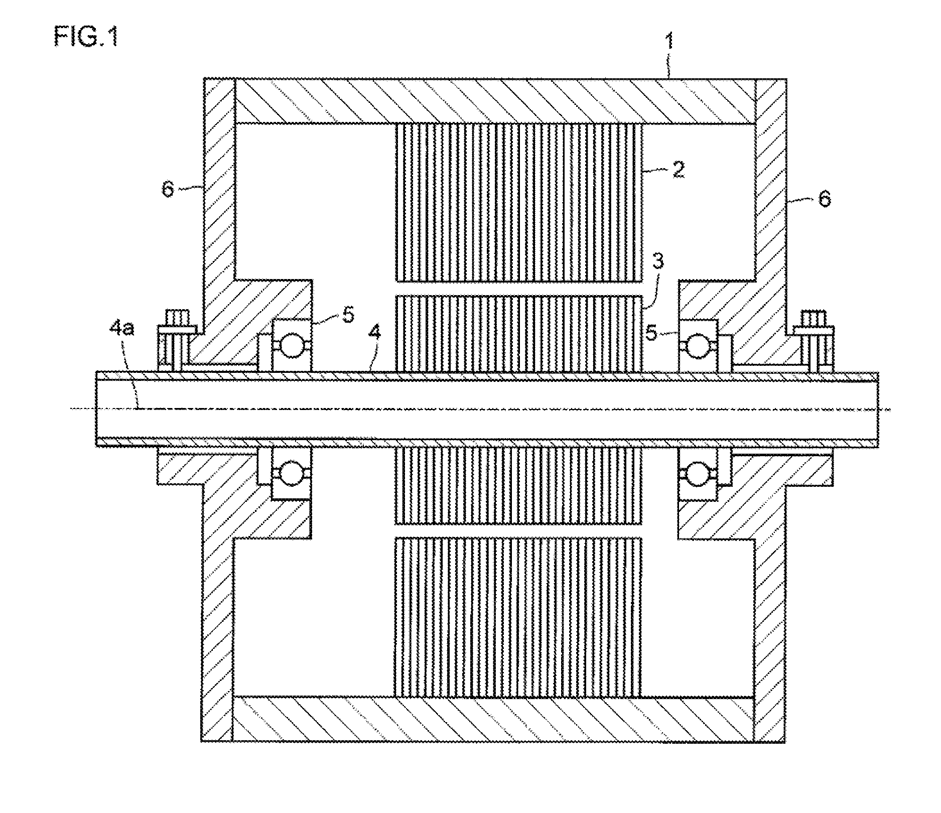
[0035]FIG. 1 is a longitudinal sectional view of an overall configuration of a permanent magnet embedded rotating electrical machine, which is an embodiment of the disclosure. In FIG. 1, a frame 1 is a housing that covers the whole of a permanent magnet embedded rotating electrical machine, and is configured of iron, aluminum, stainless steel, or the like. A fixed side iron core 2 of a hollow cylindrical form is provided on an inner side of the frame 1. The fixed side iron core 2 is formed by stacking silicon steel plates. A hole is provided in the fixed side iron core 2, and a stator winding formed of copper wire or the like is inserted through the hole (omitted from the drawing). A rotor 3, which is a rotating side iron core, is inserted on an inner side of the fixed side iron core 2 in a state sandwiching a predetermined gap between the rotor 3 and the fixed side iron core 2. The r...


PUM


Abstract

A permanent magnet embedded rotating electrical machine such that permanent magnets of a multiple of poles are embedded in an interior of a rotor of which one pole is configured by two permanent magnets has a rotor such that an outer periphery of the rotor and a magnet embedding hole housing the permanent magnet communicate. Magnet embedding holes are arrayed so as to form an inverted V-shape. An auxiliary process, which is a V-shape process, a boss process, a pinhole process, or a bolt hole process, is performed in a region between an inscribed circle of the magnet embedding hole and the outer periphery of the rotor in each rotor steel plate configuring the rotor.

Description

CROSS-REFERENCE TO RELATED APPLICATIONS[0001]This application is a continuation application, filed under 35 U.S.C. §111(a), of International Application PCT / JP2015 / 059408 filed on Mar. 26, 2015 and claims foreign priority to Japanese Patent Application No. 2014-101579, filed May 15, 2015, the content of each of which is incorporated herein by reference in its entirety.BACKGROUND[0002]1. Field[0003]The present disclosure relates to a rotating electrical machine having a rotor, such as a motor or generator, and in particular, relates to a permanent magnet embedded rotating electrical machine wherein a permanent magnet is embedded in the rotor.[0004]2. Background Art[0005]FIG. 9A and FIG. 9B are sectional views showing a rotor configuration of an IPM motor, which is one example of an existing permanent magnet embedded rotating electrical machine, and FIG. 9C is a diagram showing an outer peripheral surface of the rotor. The IPM motor of this existing example is disclosed in Japanese Ap...

Claims


Application Information

Patent Timeline
Patent Type & Authority Applications(United States)
IPC IPC(8): H02K21/14H02K15/03H02K1/27
CPCH02K21/14H02K15/03H02K1/2706H02K1/276H02K2201/09H02K1/27H02K1/2766
Inventor MOCHIDA, TOSHIHARUTOBA, AKIOSHIMADA, HIROSHINISHIMURA, HIROFUMISASAKI, NOBUYUKI
Owner FUJI ELECTRIC CO LTD
Why Eureka
Try Eureka