Systems and methods for repair redundancy control for large erasure coded data storage

a data storage and redundancy control technology, applied in the field of systems and methods for repairing redundancy control for large erasure coded data storage, can solve the problems of intermittent failure, permanent loss of data stored on the storage node, and individual storage nodes that are somewhat unreliable, and achieve the desired level of repair efficiency

Inactive Publication Date: 2017-03-02
QUALCOMM INC
View PDF13 Cites 12 Cited by
  • Summary
  • Abstract
  • Description
  • Claims
  • Application Information

AI Technical Summary

Benefits of technology

[0017]A non-transitory computer-readable medium comprising codes for controlling a source object repair rate in a storage system is provided according to yet further embodiments herein. The codes of embodiments cause a computer to analyze a plurality of source objects in a repair queue to determine at least one repair rate metric for the source objects of the plurality of source objects. The codes of embodiments furth

Problems solved by technology

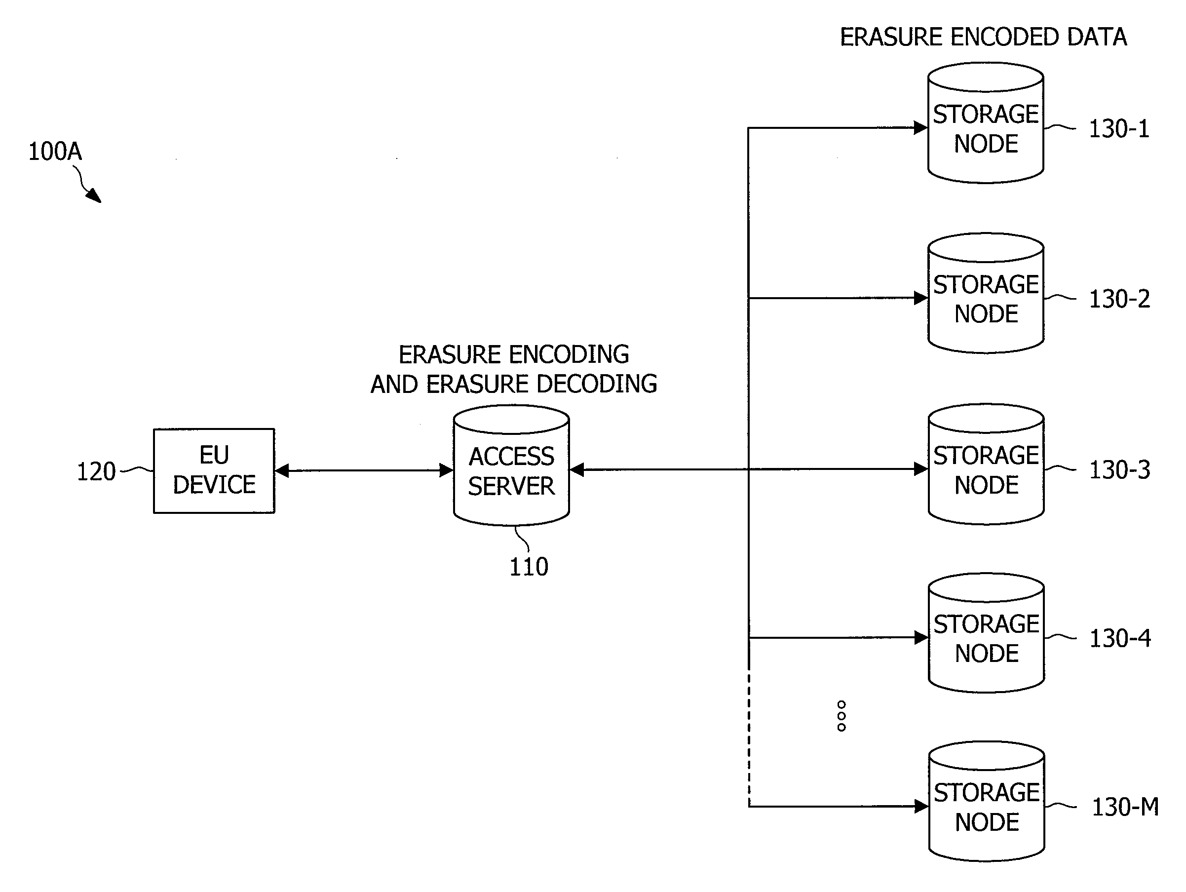
However, the individual storage nodes are somewhat unreliable in that they can intermittently fail, in which case the data stored on them is temporarily unavailable, or permanently fail, in which case the data stored on them is permanently lost (e.g., as represented by the failure of storage node 130-2 in FIG. 1C).
This can result in inefficiencies with respect to the use of resources, such as communication bandwidth, computing resources, etc.
Because a large amount of data is stored on each node (typically many terabytes), and all data comprising fragments stored on a node typically needs to be replaced when the node permanently fails, the repair process reads and writes a large amount of data after a node permanently fails.
This reading and writing of large amounts of data generally results in the consumption of large amounts of ba

Method used


Image

  • Systems and methods for repair redundancy control for large erasure coded data storage
  • Systems and methods for repair redundancy control for large erasure coded data storage
  • Systems and methods for repair redundancy control for large erasure coded data storage

Examples


Embodiment Construction

[0029]The word “exemplary” is used herein to mean “serving as an example, instance, or illustration.” Any aspect described herein as “exemplary” is not necessarily to be construed as preferred or advantageous over other aspects.

[0030]In this description, the term “application” may also include files having executable content, such as: object code, scripts, byte code, markup language files, and patches. In addition, an “application” referred to herein, may also include files that are not executable in nature, such as documents that may need to be opened or other data files that need to be accessed.

[0031]As used in this description, the terms “data” and “electronic data” may include information and content of various forms, including raw data, processed data, produced content, and / or the like, whether being executable or non-executable in nature. Such data may, for example, include data collected from sensors, monitoring devices, control systems, metrics or other results generated fro...


PUM


Abstract

Systems and methods which implement storage system data repair control techniques, such as may provide a feedback control structure for regulating source object redundancy and/or repair bandwidth in the storage system. Embodiments control a source object redundancy level to be used in a storage system by analyzing source objects represented in a repair queue to determine repair rate metrics for the source objects and determining a source object redundancy level based on the repair rate metrics. For example, embodiments may cause more redundant fragments for each source object to be generated and stored during repair where the repair rate metrics indicate an increase in storage node failure rate. Additionally, embodiments may determine a per storage object repair rate (e.g., a repair rate preference for each of a plurality of source objects) and select a particular repair rate (e.g., a maximum repair rate) for use by a repair policy.

Description

CROSS-REFERENCE TO RELATED APPLICATIONS[0001]This application claims the benefit of U.S. Provisional Patent Application No. 62 / 211,303, entitled, “SYSTEMS AND METHODS FOR REPAIR RATE CONTROL FOR LARGE ERASURE CODED DATA STORAGE”, filed on Aug. 28, 2015, which is expressly incorporated by reference herein in its entiretyDESCRIPTION OF THE RELATED ART[0002]The creation, management, storage, and retrieval of electronic data has become nearly ubiquitous in the day-to-day world. Such electronic data may comprise various forms of information, such as raw data (e.g., data collected from sensors, monitoring devices, control systems, etc.), processed data (e.g., metrics or other results generated from raw data, data aggregations, filtered data, etc.), produced content (e.g., program code, documents, photographs, video, audio, etc.), and / or the like. Such data may be generated by various automated systems (e.g., network monitors, vehicle on-board computer systems, automated control systems, e...

Claims


Application Information

Patent Timeline
IPC IPC(8): H03M13/15G06F11/10
CPCG06F11/1076H03M13/154G06F11/1088G06F11/008
Inventor RICHARDSON, THOMAS JOSEPHLUBY, MICHAEL GEORGE
Owner QUALCOMM INC
Why Eureka
Try Eureka