MEMS device, liquid ejecting head, liquid ejecting apparatus, manufacturing method of MEMS device, and manufacturing method of liquid ejecting head

a manufacturing method and technology of a liquid ejector, applied in the direction of printing, inking apparatus, etc., can solve the problems of difficult electrical connection between piezoelectric elements disposed at high density and a driving circuit, mechanical damage tends to be generated on the pressure chamber forming substrate, and more difficult to generate mechanical damage on the second substrate, etc., to achieve the effect of simplifying the manufacturing process and increasing productivity

Active Publication Date: 2017-03-09
SEIKO EPSON CORP
View PDF1 Cites 13 Cited by
  • Summary
  • Abstract
  • Description
  • Claims
  • Application Information

AI Technical Summary

Benefits of technology

[0030]In the manufacturing method according to the application example, since the groove and the through port are collectively formed by etching the fourth substr...

Problems solved by technology

It is possible to dispose the piezoelectric elements at high density by using the thin-film shape piezoelectric elements, on the other hand, electrical connection between the piezoelectric elements that are disposed at high density and a driving circuit is difficult.
However, in a case where the pressure chamber forming substrate for achieving high density of nozzles that eject liquid is manufactured using a silicon single crystal substrate, and furthermore, the pressure chamber forming substrate for increasing ejectabilty and ejection precision of liquid is thinned, in the ink jet recording h...

Method used


Image

  • MEMS device, liquid ejecting head, liquid ejecting apparatus, manufacturing method of MEMS device, and manufacturing method of liquid ejecting head
  • MEMS device, liquid ejecting head, liquid ejecting apparatus, manufacturing method of MEMS device, and manufacturing method of liquid ejecting head
  • MEMS device, liquid ejecting head, liquid ejecting apparatus, manufacturing method of MEMS device, and manufacturing method of liquid ejecting head

Examples


embodiment 1

Summary of Printer

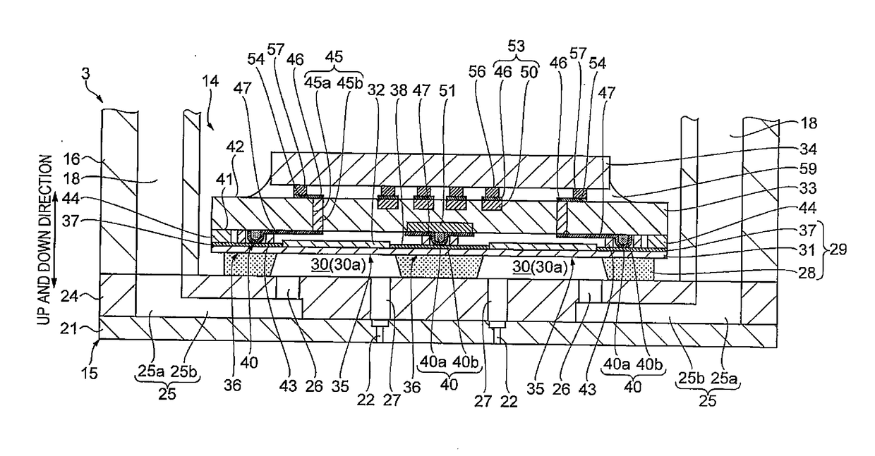
[0045]FIG. 1 is a schematic view illustrating a configuration of an ink jet recording apparatus (hereinafter, referred to as printer) according to Embodiment 1. To begin with, with reference to FIG. 1, a summary of a printer 1 that is an example of a “liquid ejecting apparatus” will be described.

[0046]The printer 1 according to the embodiment is an apparatus that ejects ink that is an example of “liquid” on a recording medium 2 such as recording paper and performs recording (printing) of an image or the like on the recording medium 2.

[0047]As shown in FIG. 1, the printer 1 is provided with a carriage 4 to which the recording head 3 is attached, a carriage moving mechanism 5 which moves the carriage 4 in a main scanning direction, a transport mechanism 6 which transfers the recording medium 2 in a sub-scanning direction, and the like. Here, the ink is retained in an ink cartridge 7 which acts as a liquid supply source. The ink cartridge 7 is mounted so as to be atta...

embodiment 2

[0135]FIG. 12 is a schematic sectional view illustrating a configuration of a recording head according to Embodiment 2.

[0136]In a recording head 3A according to the embodiment, the driving circuit 39 is formed (built in) which drives the piezoelectric element 32 on a first substrate 33G. In the recording head 3 according to Embodiment 1, a driving circuit is formed which drives the piezoelectric element 32 on a separate substrate (driving IC 34) from the first substrate 33. In this point, the recording head 3A according to the embodiment and the recording head 3 according to Embodiment 1 are different, and the other configuration is the same in the embodiment and Embodiment 1.

[0137]A summary of the recording head 3A according to the embodiment will be described below focusing on differences from Embodiment 1 with reference to FIG. 12. In addition, the same reference numerals are given for the configuration parts which are the same as in Embodiment 1, and overlapping description is o...


PUM


Abstract

A MEMS device includes a first substrate; a second substrate that is disposed laminated on the first substrate; and a functional element that is disposed between the first substrate and the second substrate, in which the second substrate is smaller than the first substrate, and in planar view, an end portion of the second substrate is disposed inside an end portion of the first substrate.

Description

CROSS-REFERENCE TO RELATED APPLICATIONS[0001]The present application claims priority to Japanese Patent Application No. 2015-176369 filed on Sep. 8, 2015, which is hereby incorporated by reference in its entirety.BACKGROUND[0002]1. Technical Field[0003]The present invention relates to a MEMS device, a liquid ejecting head which is an example of the MEMS device, a liquid ejecting apparatus which is provided with the liquid ejecting head, a manufacturing method of a MEMS device, and a manufacturing method of a liquid ejecting head.[0004]2. Related Art[0005]An ink jet recording head, which is an example of the Micro Electro Mechanical Systems (MEMS) device, has a flow path forming substrate on which a pressure chamber that retains liquid is formed and a functional element (piezoelectric element) that is provided on one surface side of the flow path forming substrate, generates pressure variation in the liquid within the pressure chamber by driving the piezoelectric element, and ejects ...

Claims


Application Information

Patent Timeline
IPC IPC(8): B41J2/14B41J2/16
CPCB41J2/14233B41J2/1626B41J2/161B41J2/1623B41J2/045B41J2/1629B41J2/1631B41J2/1632B41J2/1634B41J2/1646B41J2002/14362B41J2002/14491B41J2202/18B41J2002/1425
Inventor HIRAI, EIJUNAGANUMA, YOICHIHAMAGUCHI, TOSHIAKITAKABE, MOTOKI
Owner SEIKO EPSON CORP
Why Eureka
Try Eureka