
Apparatus, systems, and methods for pre-heating feedstock to a melter using melter exhaust

Active Publication Date: 2017-03-09
JOHNS MANVILLE CORP
View PDF1 Cites 16 Cited by
  • Summary
  • Abstract
  • Description
  • Claims
  • Application Information

AI Technical Summary

Benefits of technology

The present invention is about improving submerged combustion burners that are used to make molten glass and other non-metallic inorganic materials, such as rock wool and mineral wool. The improvements can help to resolve issues that were previously associated with these burners.

Problems solved by technology

The introduction of high flow rates of products of combustion of the oxidant and fuel into the molten material, and the expansion of the gases during submerged combustion (SC), cause rapid melting of the feedstock and much turbulence and foaming.
Despite the reduction of the flue gas volume that the substitution of combustion with air by combustion with pure oxygen or oxygen-enriched air yields, a significant amount of energy is lost in the flue gas (also referred to herein as exhaust or exhaust gases), especially for high temperature processes.
Experience shows that this technology is difficult to operate when the batch represents more than 50% of the raw materials because of a tendency to plug.
This limits the applicability of the technique to a limited number of glass melting operations that use a large fraction of cullet.
Another drawback of this technique (according to the known art) is that the inlet temperature of the flue gas in the materials preheater must be generally kept lower than 600° C. in the case of an oxy-fuel fired furnace where the flue gas is produced at a temperature higher than 1000° C., one reference (U.S. Pat. No. 6,250,916) discloses that cooling of the flue gas prior to the materials preheater would be required.
This would be counterproductive.

Method used


Image

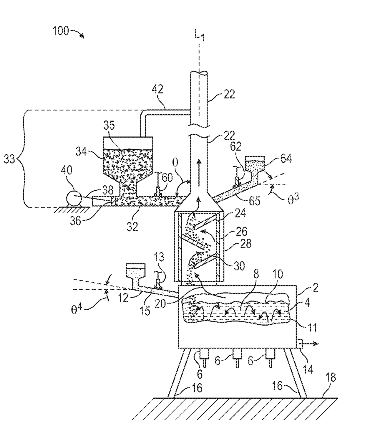
  • Apparatus, systems, and methods for pre-heating feedstock to a melter using melter exhaust
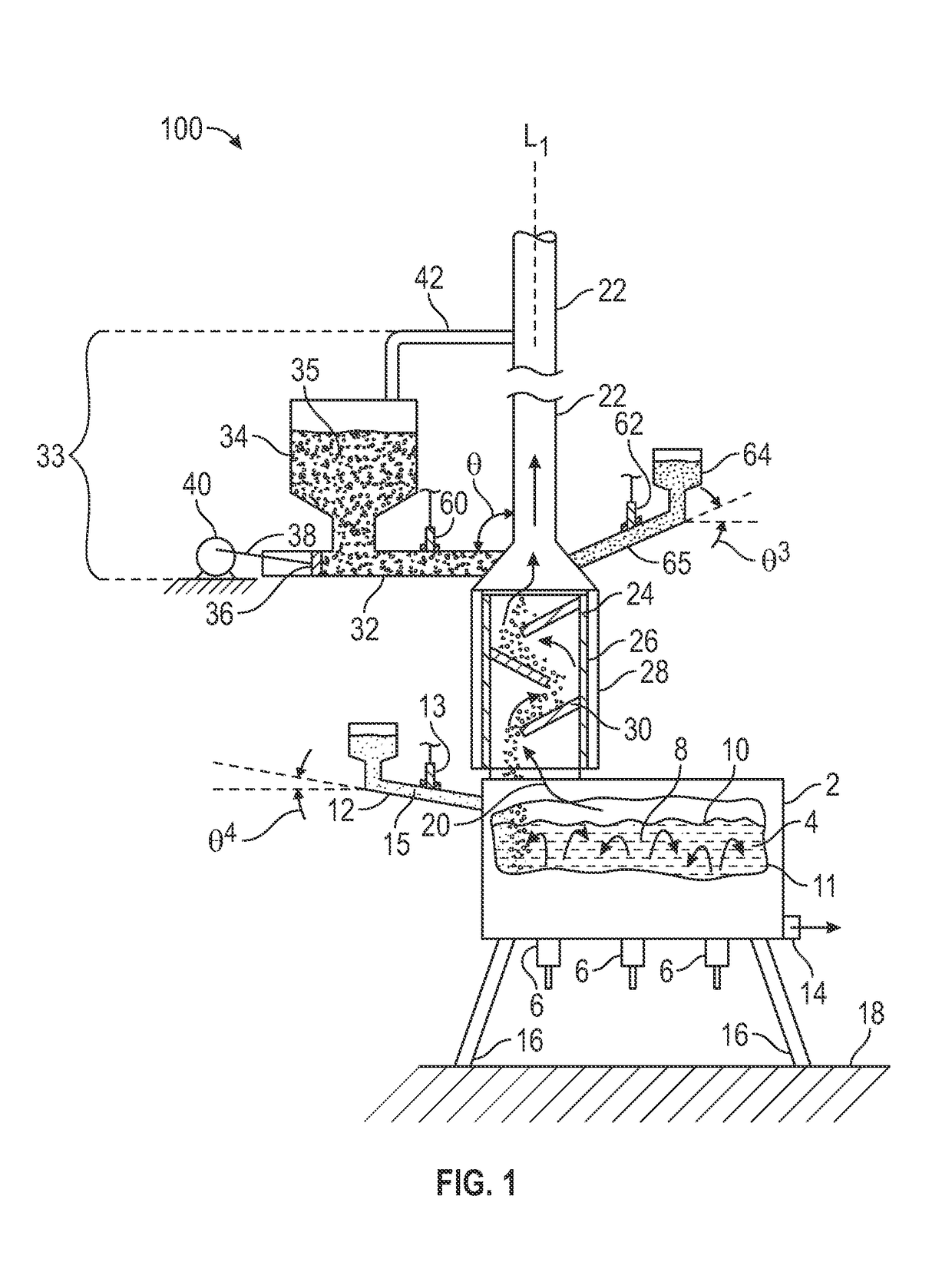
  • Apparatus, systems, and methods for pre-heating feedstock to a melter using melter exhaust
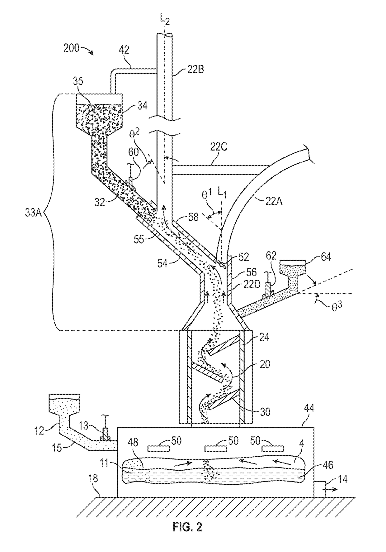
  • Apparatus, systems, and methods for pre-heating feedstock to a melter using melter exhaust

Examples


Embodiment Construction

[0028]In the following description, numerous details are set forth to provide an understanding of the disclosed systems, apparatus, and methods. However, it will be understood by those skilled in the art that the systems, apparatus, and methods covered by the claims may be practiced without these details and that numerous variations or modifications from the specifically described embodiments may be possible and are deemed within the claims. For example, wherever the term “comprising” is used, embodiments and / or components where “consisting essentially of” and “consisting of” are explicitly disclosed herein and are part of this disclosure. All published patent applications and patents referenced herein are hereby explicitly incorporated herein by reference. In the event definitions of terms in the referenced patents and applications conflict with how those terms are defined in the present application, the definitions for those terms that are provided in the present application shall...


PUM

PropertyMeasurementUnit
Angleaaaaaaaaaa
Angleaaaaaaaaaa
Angleaaaaaaaaaa

Abstract

Feedstock supply structure apparatus, including an exhaust conduit fluidly and mechanically connectable to a structure defining a melting chamber, the exhaust conduit positioned at an angle to vertical ranging from 0 to about 90 degrees. The exhaust conduit may include a heat exchange substructure, or the conduit itself may serve as a heat exchanger. A feedstock supply structure fluidly connected to the exhaust conduit. Systems include a structure defining a melting chamber and an exhaust conduit fluidly connected to the structure. The exhaust conduit includes a heat exchange substructure for preheating the feedstock. Methods include supplying a granular or pellet-sized feedstock to the melter exhaust conduit, the exhaust conduit including the heat exchange substructure, and preheating the feedstock by indirect or direct contact with melter exhaust in the heat exchange substructure.

Description

BACKGROUND INFORMATION[0001]Technical Field[0002]The present disclosure relates generally to the field of combustion melters and apparatus, and methods of use, and more specifically to submerged and conventional combustion melters, and methods of their use, particularly for melting glass-forming materials, mineral wool forming materials, and other non-metallic inorganic materials.[0003]Background Art[0004]A submerged combustion melter (SCM) may be employed to melt glass batch and / or waste glass materials to produce molten glass, or may melt mineral wool feedstock to make mineral or rock wool, by passing oxygen, oxygen-enriched mixtures, or air along with a liquid, gaseous and / or particulate fuel (some of which may be in one or more of the feedstock materials), directly into a molten pool of glass or other material, usually through burners submerged in a turbulent melt pool. The introduction of high flow rates of products of combustion of the oxidant and fuel into the molten material...

Claims


Application Information

Patent Timeline
IPC IPC(8): C03B3/02C03B5/235
CPCC03B3/023C03B2211/22C03B5/2356Y02P40/50
Inventor HUBER, AARON MORGAN
Owner JOHNS MANVILLE CORP
Learn More