Electromagnetic Valve

a technology of electromagnetic valves and electromagnetic valves, applied in the direction of valve operating means/release devices, stress-reducing fuel injection, machines/engines, etc., can solve the problems of increasing the amount of injection, reducing the fuel consumption and combustion properties, and reducing the stress of injection, so as to reduce stress and reduce the amount of injection

Active Publication Date: 2017-03-16
HITACHI ASTEMO LTD
View PDF2 Cites 3 Cited by
  • Summary
  • Abstract
  • Description
  • Claims
  • Application Information

AI Technical Summary

Benefits of technology

[0015]According to the present invention, by reducing stress occurred on the collision structural part, wear and deformation can be suppressed by a high productive method.

Problems solved by technology

This configuration leads to an increase of an injection amount and a decrease of the fuel consumption and the combustion property.

Method used


Image

  • Electromagnetic Valve
  • Electromagnetic Valve
  • Electromagnetic Valve

Examples


first embodiment

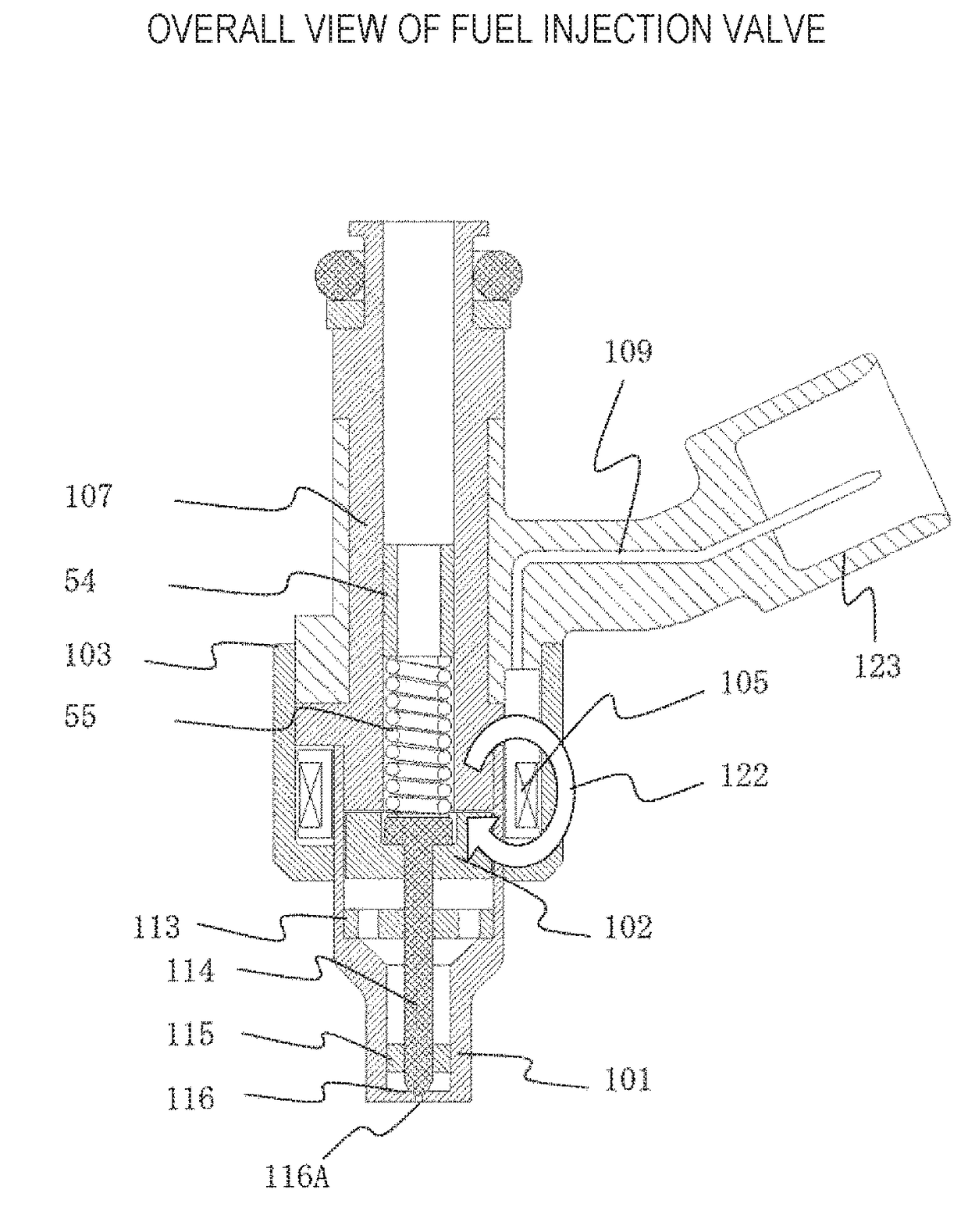
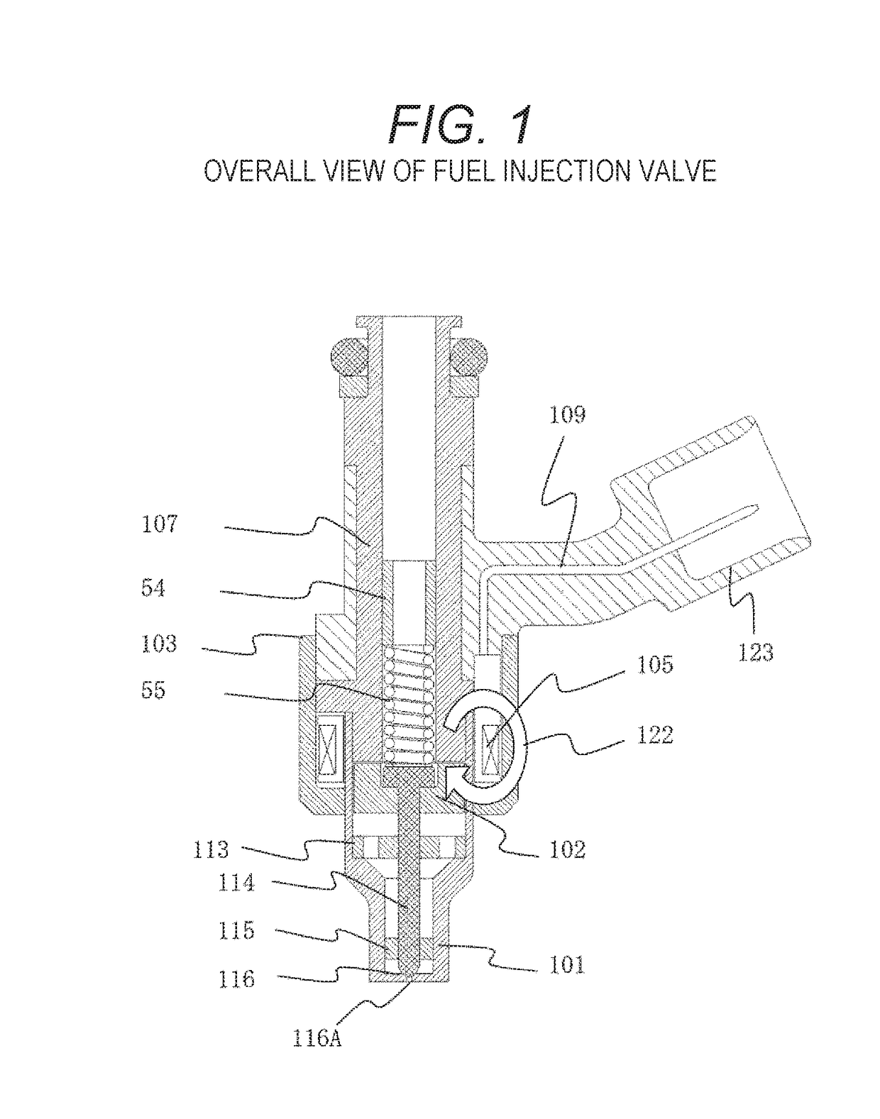
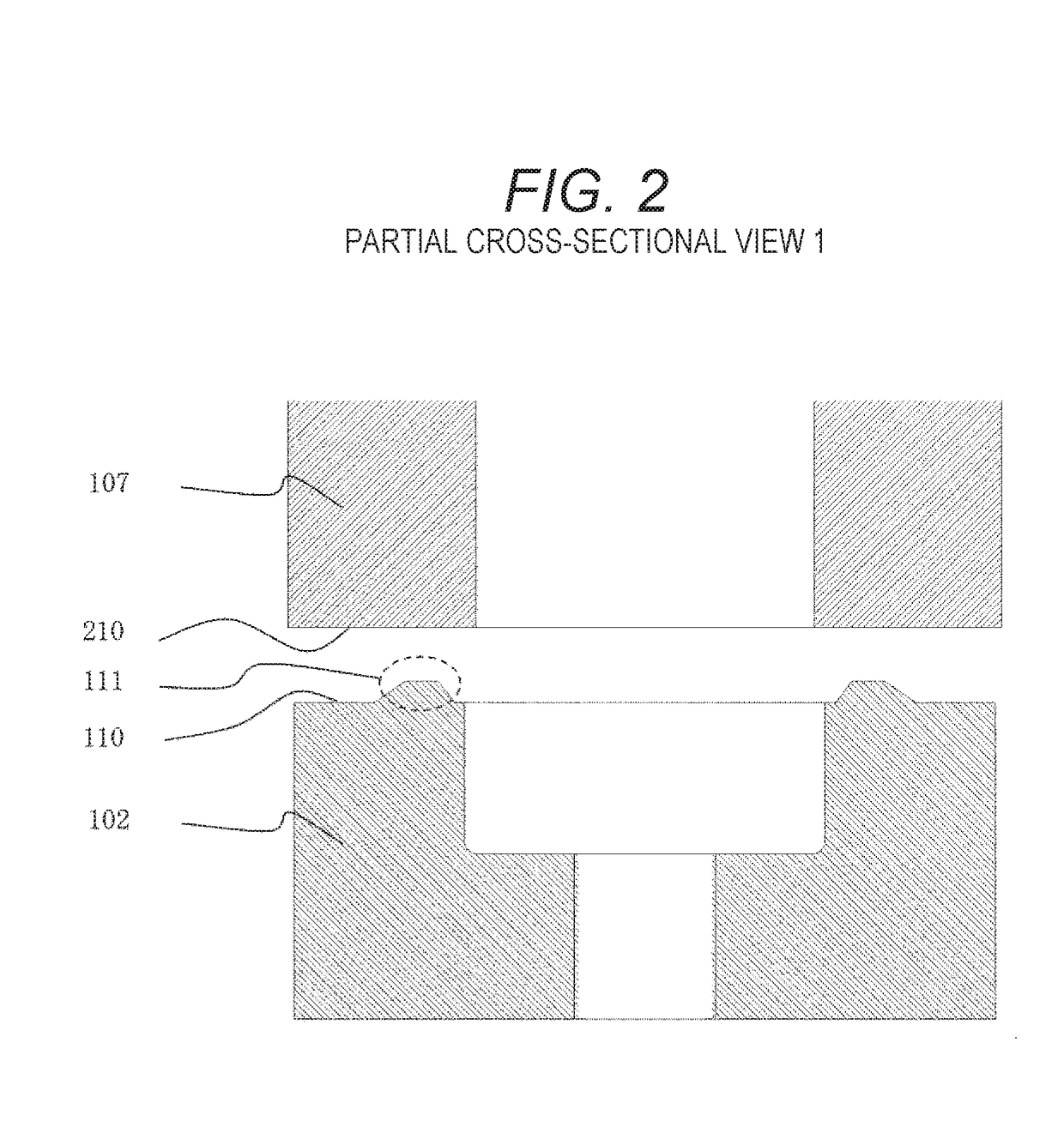
[0035]A first embodiment is described with reference to FIGS. 2 and 3.

[0036]As shown in FIG. 2, the fixed core and the movable core respectively have a ring shaped end surface 110 and end surface 210 facing each other. A projection 111, which is contacted with the fixed core end surface 210 in colliding, is provided on the movable core end surface 110. The fixed core and the movable core are collided with each other in valve opening and therefore the end surface 210 and the projection 111 are contacted with each other.

[0037]When the end surface 110 and the end surface 210 are contacted with each other in liquid, a valve closing time is extended because squeezing force defined by adhering force of the liquid is generated and therefore a response property is deteriorated. Thus, a contact area is narrowed as much as possible by providing the projection 111 and generation of the squeezing force is suppressed.

[0038]Further, in a case in which the end surface 210 and a part of the end sur...

second embodiment

[0048]A second embodiment is described with reference to FIGS. 6(a) to 6 (c). FIG. 6(a) shows a configuration in which the flat 24 is disappeared because the inner diameter taper 25 is shifted. toward. the outer peripheral side, while the R-shaped part 23 is completely remained. In this case, since the R-shaped part 13 and the flat part 14 are connected in a tangent manner after plating, even if the inclined angle θ is small, the occurred stress is suppressed.

[0049]On the other hand, a configuration to which the present embodiment is not applied is described for the sake of explanation with reference to FIGS. 6 (b) and 6 (c). When the inner peripheral taper 25 is shifted toward the outer peripheral side (left side in figure) in a case in which the flat 24 is not formed, or when the inner per taper 25 is shifted toward the outer peripheral side beyond a region of the flat 24, as shown in FIG. 6 (b) , the R-shaped part 23 is not connected with the connecting part of the flat part 14 i...


PUM


Abstract

It is important not to form the partial bump in the collision structural part, however the fixed core and the movable core are relatively inclined due to an accumulation of tolerances and therefore even if each collision structural part of the fixed core and the movable core in formed in a flat shape, the fixed core and the movable core are contacted with not the whole of the collision structural parts but a part of the collision structural parts at the moment of the collision. In a case in which the collision structural part is formed in a ring shape or an intermittent ring shape, the fixed core and the movable core are contacted with each other at outer peripheral parts. Thus, when the fixed core and the movable core are collided with each other, a high stress is applied to the outer peripheral parts contacted first. Accordingly, the shape of the outer peripheral parts of the collision structural parts is important, however since such a part, which is a tiny protruding shape, requires high processing accuracy, to reduce stress occurred during collision while keeping productivity is difficult. In the present invention, an R-shaped part and a flat part are provided in order from an outer peripheral side of a collision structural part. Further, the R-shaped part and the flat part are connected in a tangent manner.

Description

TECHNICAL FIELD[0001]The present invention relates to a solenoid type electromagnetic valve.BACKGROUND ART[0002]In an electromagnetic type fuel injection valve used in an internal combustion engine, in particular, a cylinder injection system for vehicle using gasoline, in order to satisfy the regulation or the demand with respect to exhaust gas or fuel consumption, there has been an increasing market demand for injecting fuel into an engine cylinder at a higher pressure compared to a conventional way of injecting. It is because the injection speed of fuel is increased and frictional, resistance between air and fuel becomes larger as the fuel pressure becomes higher, and therefore the fuel is further atomized, as a result, a combustion property is improved.[0003]The electromagnetic type fuel injection valve is formed as a solenoid type valve which opens the valve, by attracting movable core formed as a movable iron core by a magnetic attraction force toward a fixed core formed as a f...

Claims


Application Information

Patent Timeline
Patent Type & Authority Applications(United States)
IPC IPC(8): F02M51/06F16K31/06F16K1/12
CPCF02M51/0671F16K1/12F16K31/0675F02M2200/9061F02M2200/03F02M2200/9038F02M2200/02F02M2200/08
Inventor TAKAOKU, ATSUSHIYANAGISAWA, YUTAOGURA, KIYOTAKA
Owner HITACHI ASTEMO LTD
Why Eureka
Try Eureka