
Storage system

a storage system and deduplication technology, applied in the field of storage systems, can solve the problems of flash memory not having compatibility with hdds, flash memory cannot directly overwrite update data, flash memory has higher bit cost than magnetic disks, etc., and achieves the effect of small performance degradation and high efficiency

Active Publication Date: 2017-03-16
HITACHI LTD
View PDF4 Cites 33 Cited by
  • Summary
  • Abstract
  • Description
  • Claims
  • Application Information

AI Technical Summary

Benefits of technology

The present invention relates to a technology that can efficiently remove redundancy in a large-capacity storage system with multiple flash packages. This technology can allocate more capacity than the physical capacity of the flash packages and has high efficiency and minimal performance degradation. Additionally, this technology can also be used with hard disk drives and other storage devices.

Problems solved by technology

When rewriting data in a flash memory, the characteristic feature of the flash memory does not allow direct overwrite of update data to a physical area where the original data has been stored.
However, there are some storage devices that do not have compatibility with HDDs.
However, flash memories have higher bit costs compared to magnetic disks and the like, so there is a strong demand to reduce the capacity of stored data and increase apparent capacity (amount of data that can be stored from higher-level devices such as host computers).
This technology utilizes the characteristic feature that when the user actually uses the storage, the amount of data actually stored in the system does not easily reach the capacity of the volume defined by the user (capacity of the storage device seen from the user).
When compression is performed, the data length after compression differs in each data update, so that there are many cases where data cannot be stored in the area where the data had been originally stored.

Method used


Image

  • Storage system
  • Storage system
  • Storage system

Examples


embodiment 1

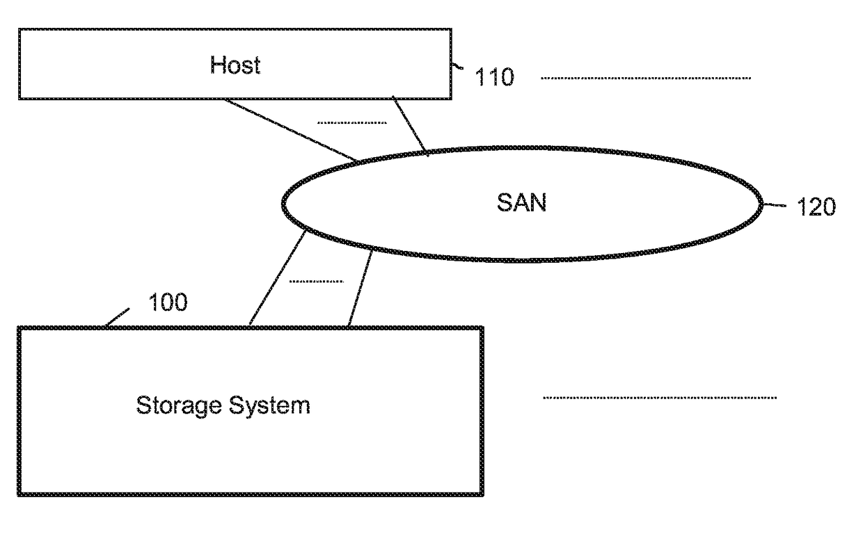
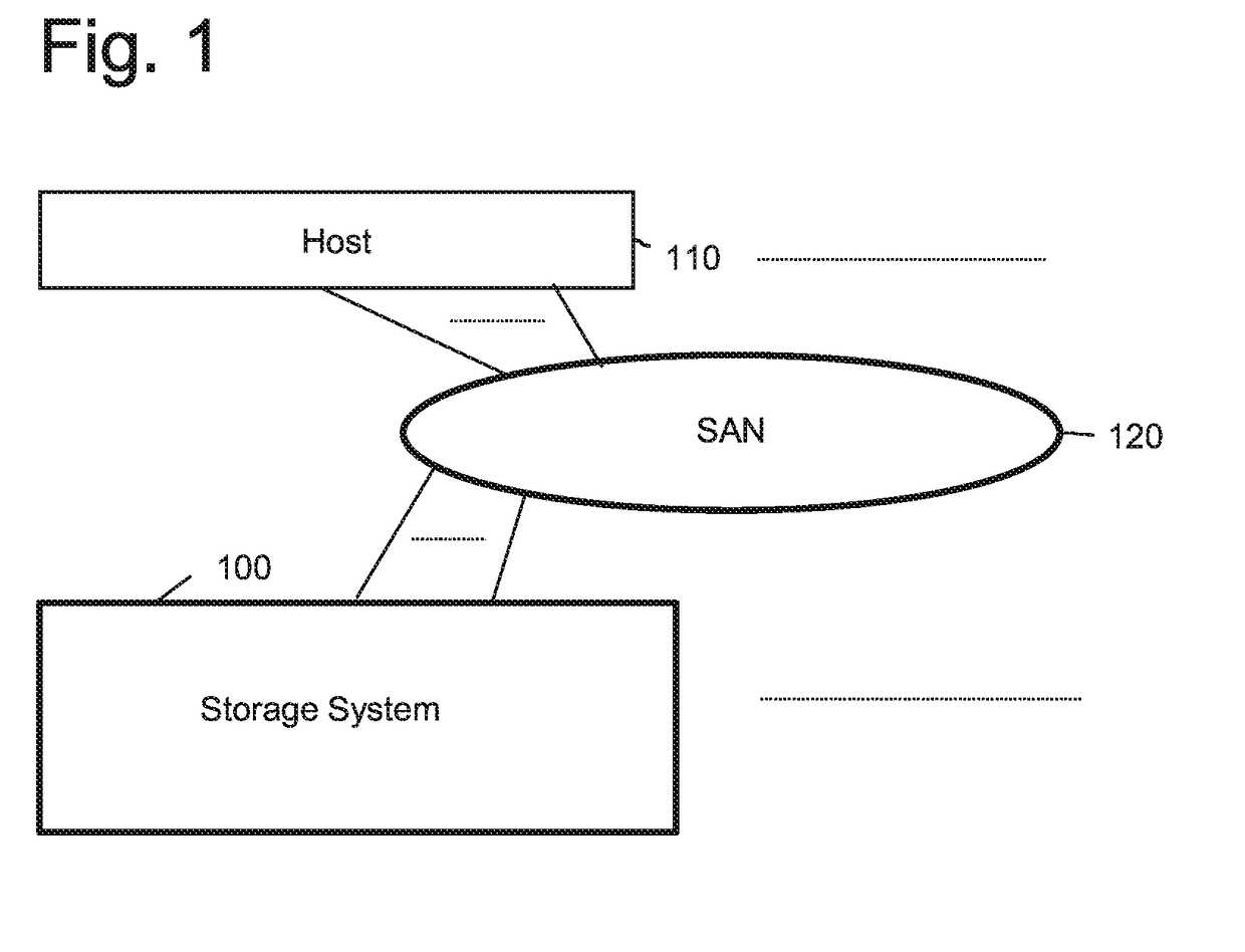
[0064]FIG. 1 is a view showing a configuration of an information system according to a preferred embodiment of the present invention. The information system is composed of a storage system 100, a host 110, and a SAN (Storage Area Network) 120 coupling these components. The host 110 is a system in which a user application is executed, and it reads and write required data back and forth to the storage system 100 via the SAN 120. The SAN 120 uses a protocol capable of transferring SCSI commands. For example, a Fibre Channel or other protocols can be used. The present invention is also effective in a configuration where the host 110 and the storage system 100 are directly coupled.

[0065]The present embodiment realizes a technology for reducing the capacity of data stored in a flash memory through a deduplication process in the storage system 100 comprising a large number of flash memories as storage media. In the first embodiment, the storage system 100 has a hierarchical capacity virtua...

embodiment 2

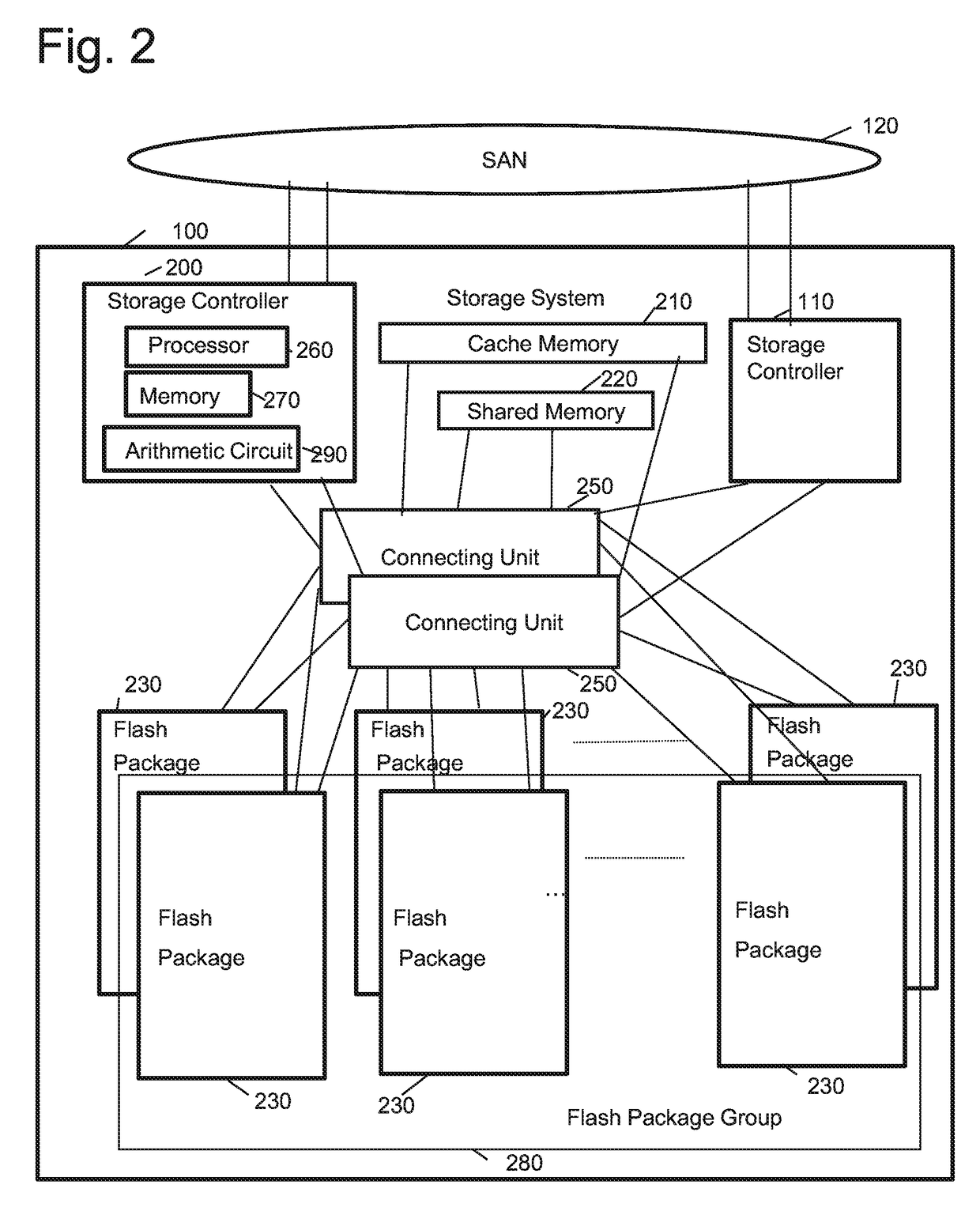
[0302]Next, the second embodiment of the present invention will be described. The hardware configurations of the information system, the storage system, and the flash package according to Embodiment 2 are the same as the first information system. However, the storage system 200 according to the second embodiment differs from the storage system 200 of the first embodiment in that the flash package 230 does not constitute a flash package group 280.

[0303]Also according to the storage system 200 of the second embodiment, the flash package 230 has a deduplication function, but in the second embodiment, the storage controller 200 improves the deduplication rate by appropriately controlling the data storage destination. Specifically, the storage controller 200 calculates the feature value of the data to be written, and based on the calculated feature value, determines the flash package 230 which is the data storage destination. For example, if a plurality of data having the same features v...


PUM


Abstract

A storage system according to the present invention has a plurality of flash packages equipped with a deduplication function. When a storage controller transmits a write data and a feature value of write data to a flash package, the flash package compares contents of the write data with data having a same feature value as the feature value of the write data. As a result of the comparison, if there is no corresponding data, the write data is stored in the flash memory, but if there is a corresponding data, the new data will not be stored. Thus, a greater number of data can be stored in the flash memory while preventing deterioration of performance.

Description

TECHNICAL FIELD[0001]The present invention relates to a deduplication technology in a storage system.BACKGROUND ART[0002]When rewriting data in a flash memory, the characteristic feature of the flash memory does not allow direct overwrite of update data to a physical area where the original data has been stored. In order to rewrite data, the update data must be written to a different area instead of to the area where the original data has been stored. Identical data are written in a plurality of areas, and when the blocks become full, only the newest data stored in the blocks are transferred to unused blocks, and thereafter, a delete process is performed to the blocks not storing the relevant newest data, to thereby create free blocks. In the following description, this process will be called a reclamation process. For this reason, in a storage device equipped with flash memories, a logical address layer having an address that differs from a physical address is provided as an addres...

Claims


Application Information

Patent Timeline
Patent Type & Authority Applications(United States)
IPC IPC(8): G06F3/06
CPCG06F3/0641G06F3/0688G06F3/0659G06F3/0608G06F12/084G06F12/0866G06F12/0871G06F12/0873G06F12/1009G06F12/109G06F2212/1044G06F2212/1048G06F2212/2022G06F2212/263G06F2212/466G06F2212/657G06F16/137G06F16/174G06F12/0246G06F11/1004
Inventor YAMAMOTO, AKIRAOGAWA, JUNJISHIMOZONO, NORIOYOSHII, YOSHIHIROHIRONAKA, KAZUEIKAWAMURA, ATSUSHI
Owner HITACHI LTD
Learn More