Startup Circuit for Reference Circuits

a reference circuit and start-up circuit technology, applied in the direction of power conversion systems, instruments, process and machine control, etc., can solve the problems of self-turning off the start-up circuit , significant instability, bandgap reference circuit configuration, etc., to improve stability and robustness over process, voltage and temperature.

Active Publication Date: 2017-03-16
TEXAS INSTR INC
View PDF0 Cites 3 Cited by
  • Summary
  • Abstract
  • Description
  • Claims
  • Application Information

AI Technical Summary

Benefits of technology

[0013]Disclosed embodiments provide a start-up circuit for a voltage or current reference circuit that provides improved stability and robustness over process, voltage, and temperature.

Problems solved by technology

The high gain loop presented by this arrangement start-up circuit 20 is a significant source of instability in the overall bandgap reference circuit configuration.
This conventional self-turn-off start-up circuit 20′ also has several limitations, particularly as used in modern power-aware integrated circuits.
A first limitation is that no “handshaking” between start-up circuit 20′ and the reference circuit that it is starting up.
This absence of handshaking control can result in significant power consumption if start-up circuit 20′ is slow or has failed.

Method used


Image

  • Startup Circuit for Reference Circuits
  • Startup Circuit for Reference Circuits
  • Startup Circuit for Reference Circuits

Examples


Embodiment Construction

[0026]The one or more embodiments described in this specification are implemented into a start-up circuit for voltage and current reference circuits realized by way of complementary metal-oxide-semiconductor (CMOS) technology, as it is contemplated that such implementation is particularly advantageous in that context. However, it is also contemplated that concepts of this invention may be beneficially applied to other applications, for example according to MOS, bipolar, and BiCMOS technologies. Accordingly, it is to be understood that the following description is provided by way of example only, and is not intended to limit the true scope of this invention as claimed.

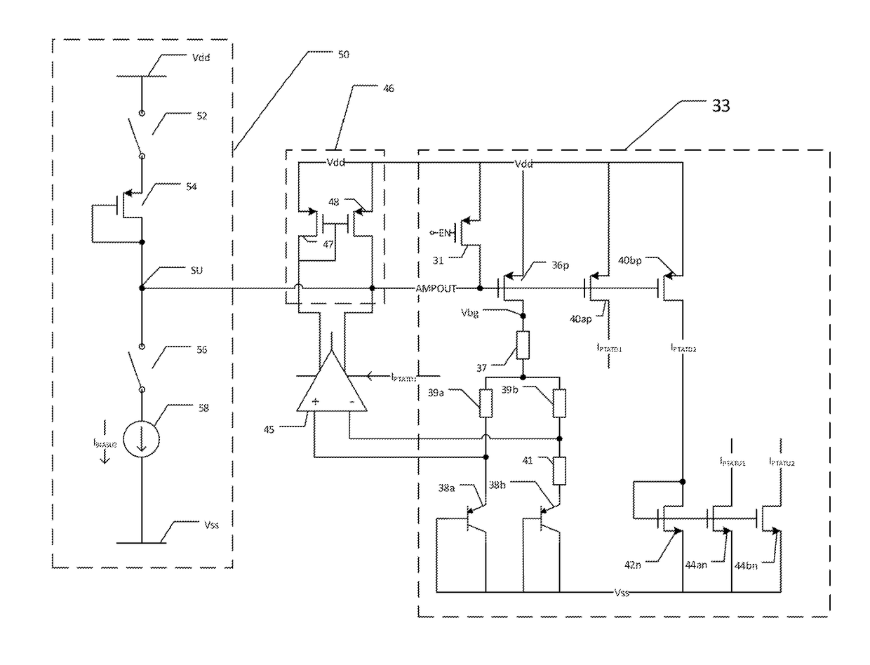
[0027]Referring now to FIG. 3, a reference circuit including a start-up circuit according to an embodiment will now be described. In this embodiment, the reference circuit includes bandgap reference circuit 33, which is constructed largely in the conventional manner as described above relative to FIG. 1b. Specifically, ...


PUM


Abstract

A start-up circuit for a reference circuit such as a bandgap reference circuit. The start-up circuit includes a diode-connected metal-oxide-semiconductor (MOS) transistor connected between a power supply node and a start-up node that is connected in turn to the gate of a current control MOS transistor in the reference circuit. The diode-connected MOS transistor and the current control MOS transistor are matched with one another. To start up the reference circuit, current is conducted through the diode-connected MOS transistor to set the gate voltage of the current control transistor at a threshold voltage below the power supply voltage. Current conducted by the current control transistor initiates operation of the bandgap reference circuit, and disables the start-up circuit.

Description

CROSS-REFERENCE TO RELATED APPLICATIONS[0001]Not applicable.STATEMENT REGARDING FEDERALLY SPONSORED RESEARCH OR DEVELOPMENT[0002]Not applicable.BACKGROUND OF THE INVENTION[0003]This invention is in the field of voltage and current reference circuits as used in integrated circuits. Embodiments are directed to startup circuits for such reference circuits.[0004]The powerful computational and operation functionality provided by modern integrated circuits has enabled the more widespread distribution of computing power in larger-scale systems. One example of such distributed electronic functionality is the so-called “Internet of Things” (IoT) contemplates the widespread deployment of electronic devices as sensors and controllers, with networked communications among those devices. Modern smartphones and wearables also deploy computational and operational functionality into a large number of distributed nodes; implantable medical devices constitute another type of distributed functionality....

Claims


Application Information

Patent Timeline
Patent Type & Authority Applications(United States)
IPC IPC(8): H02M1/36G05F3/26
CPCG05F3/267H02M1/36
Inventor QAIYUM, ASIFARNOLD, MATTHIAS
Owner TEXAS INSTR INC
Why Eureka
Try Eureka