
Magnetic assembly

a technology of magnetic assembly and winding, which is applied in the direction of transformer/inductance magnetic cores, basic electric elements, electrical equipment, etc., can solve the problems of difficult dissipation of heat generated by litz wires, loss of magnetic assembly containing core loss and winding loss, and very critical volume, weight, loss and cost of magnetic assembly, etc., to achieve the effect of reducing winding loss, increasing the volume of magnetic assembly, and reducing winding loss

Active Publication Date: 2017-03-23
DELTA ELECTRONICS (SHANGHAI) CO LTD
View PDF5 Cites 0 Cited by
  • Summary
  • Abstract
  • Description
  • Claims
  • Application Information

AI Technical Summary

Benefits of technology

The present invention provides a magnetic assembly with optimized winding parts that reduces winding loss, even at high frequencies. This results in a smaller switching power supply apparatus.

Problems solved by technology

The volume, weight, loss and cost of the magnetic assembly are very critical to the switching power supply apparatus.
Generally, the loss of the magnetic assembly contains core loss and winding loss.
However, since each strand of the Litz winding is covered with an insulation layer and the Litz wire comprises many strands, the Litz winding has a small filling factor and the heat generated by the Litz wire is difficultly dissipated.
Moreover, in comparison with the foil winding assembly, the Litz winding assembly is detrimental to the flat design and mass production.
However, it is not an optimized option for the magnetic assembly, and the total winding loss of the magnetic assembly with this foil winding assembly is still very high.

Method used


Image

  • Magnetic assembly
  • Magnetic assembly
  • Magnetic assembly

Examples


Embodiment Construction

[0023]The present invention will now be described more specifically with reference to the following embodiments. It is to be noted that the following descriptions of preferred embodiments of this invention are presented herein for purpose of illustration and description only. It is not intended to be exhaustive or to be limited to the precise form disclosed.

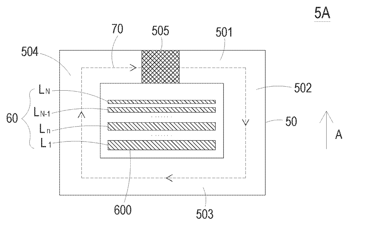
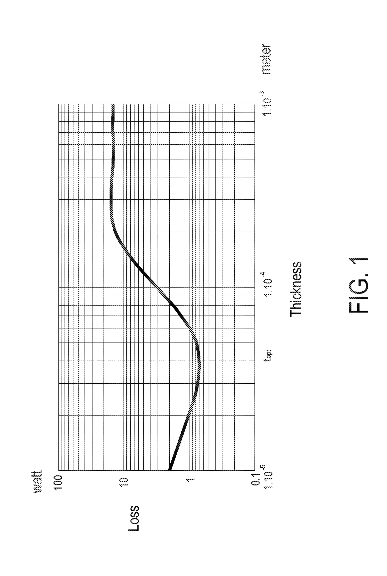
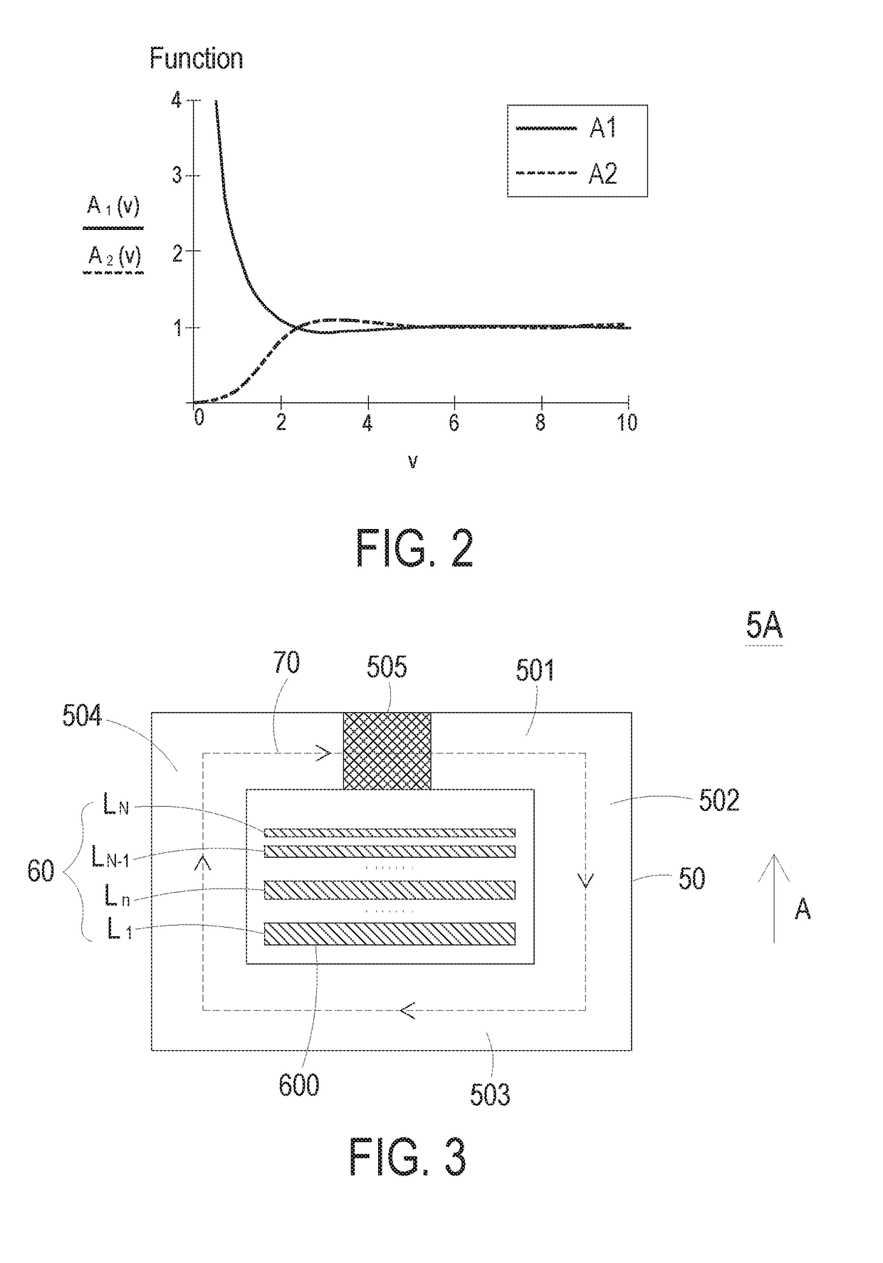
[0024]The present invention provides a magnetic assembly. The magnetic assembly uses an optimized foil winding assembly to reduce the winding loss. In the high-frequency application, the winding loss varies with the conductor thickness of the winding part because of the skin effect and the proximity effect. For reducing the winding loss, it is necessary to acquire the optimized thickness of each winding part when the skin effect and the proximity effect are taken into consideration. FIG. 1 is a plot illustrating the relationship between the conductor thickness and the loss of a general magnetic assembly. As shown in FIG. 1, the t...


PUM

PropertyMeasurementUnit
thicknessaaaaaaaaaa
thicknessaaaaaaaaaa
permeabilityaaaaaaaaaa

Abstract

A magnetic assembly includes a magnetic core and at least one foil winding assembly. The magnetic core includes plural magnetic legs. At least one magnetic path is defined by the plural magnetic legs collaboratively. Moreover, at least one low-permeability structure is formed in at least one specified magnetic leg of the plural magnetic legs. The at least one foil winding assembly is wound around the specified magnetic leg. Consequently, plural winding parts in a multi-layered arrangement are sequentially stacked on the specified magnetic leg. A direction of a conductor thickness of each winding part is perpendicular to a direction of a magnetic flux through the specified magnetic leg. The plural winding parts are gradually close to the low-permeability structure along an arranging direction, and the conductor thicknesses of at least two of the plural winding parts are gradually decreased along the arranging direction.

Description

FIELD OF THE INVENTION[0001]The present invention relates to a magnetic assembly, and more particularly to a magnetic assembly with an optimized foil winding assembly in order to reduce the winding loss.BACKGROUND OF THE INVENTION[0002]Recently, switching power supply apparatuses are developed toward miniaturization or high power density. Generally, the switching power supply apparatus comprises a magnetic assembly (e.g., an inductor or a transformer). The volume, weight, loss and cost of the magnetic assembly are very critical to the switching power supply apparatus. As known, the increase of switching frequency of the switching power supply apparatus can reduce the volume of the magnetic assembly and increase the power density of the switching power supply apparatus. As the frequency of the switching power supply apparatus is increased, the requirement of designing the magnetic assembly becomes more stringent. In the high-frequency application, it is important to reduce the loss o...

Claims


Application Information

Patent Timeline
Patent Type & Authority Applications(United States)
IPC IPC(8): H01F27/28H01F27/24
CPCH01F27/2847H01F2027/2857H01F27/24H01F27/08H01F27/28H01F27/346H01F2003/106
Inventor ZHOU, JINPINGMEI, XIULIZHOU, MIN
Owner DELTA ELECTRONICS (SHANGHAI) CO LTD
Learn More