Switching valve

a technology of switching valve and control fluid, which is applied in the direction of valve operating means/release devices, magnets, magnetic bodies, etc., can solve the problems of large switching valve, controlled fluid leakage through the packing, and large control fluid, and achieves superior durability, high reliability, and low power consumption.

Inactive Publication Date: 2017-03-30
MITSUBISHI HEAVY IND LTD
View PDF17 Cites 9 Cited by
  • Summary
  • Abstract
  • Description
  • Claims
  • Application Information

AI Technical Summary

Benefits of technology

[0028]The switching valve according to the present invention has advantages of having high reliability even in env...

Problems solved by technology

However, in applications for performing switching control of cryogenic fluid having small molecules such as in applications for performing switching control of liquid hydrogen or liquid oxygen, a problem with regard to leakage of the controlled fluid through the packing occurs.
If the pushing force of the packing toward the inner surface of the cylinder is insufficient or the packing is hardened, there is a pos...

Method used


Image

  • Switching valve
  • Switching valve
  • Switching valve

Examples


Embodiment Construction

[0034]With reference to the accompanying drawings, some embodiments of the switching valve according to the present invention will be described below.

(Configuration of Switching Valve 10)

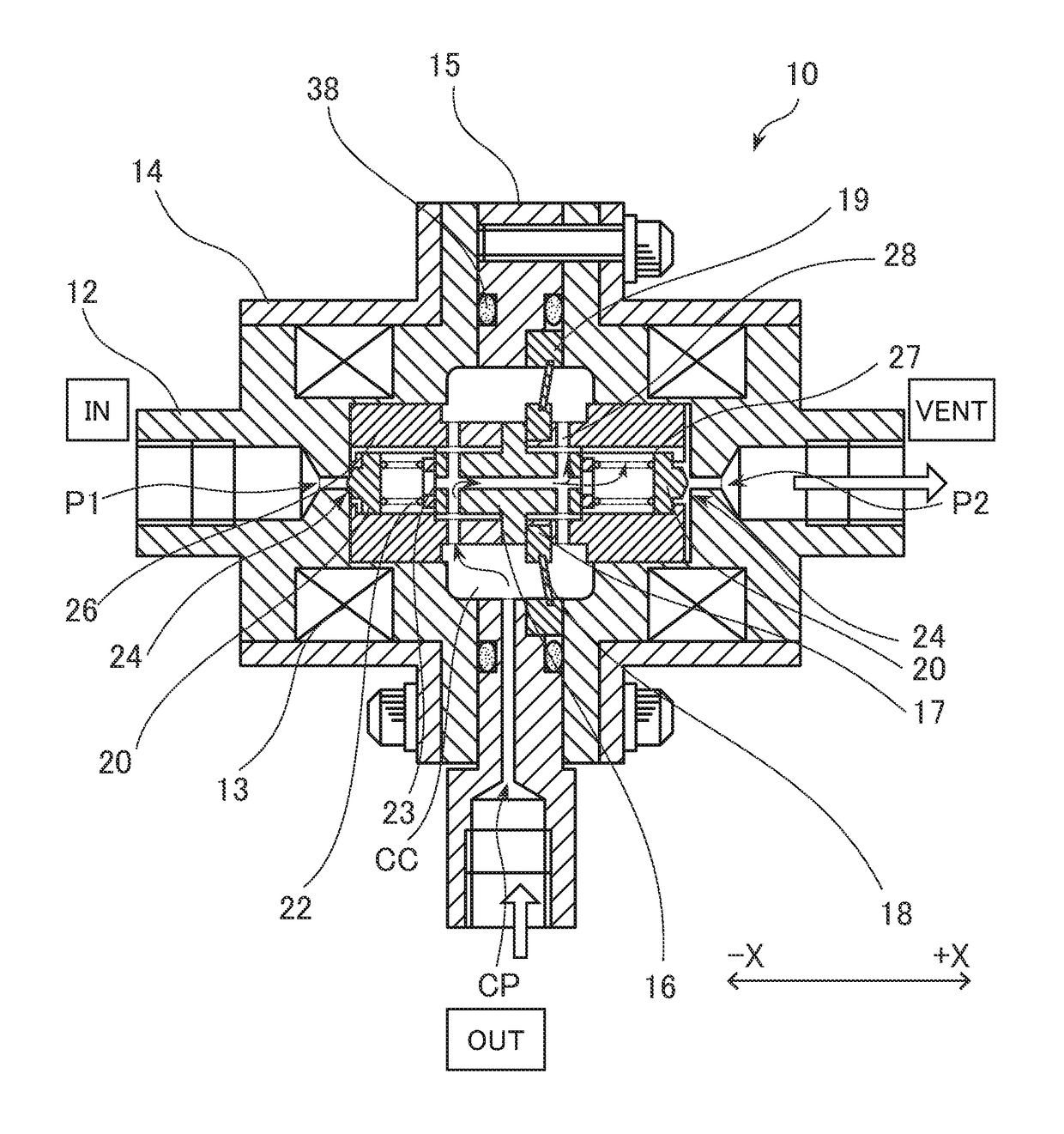
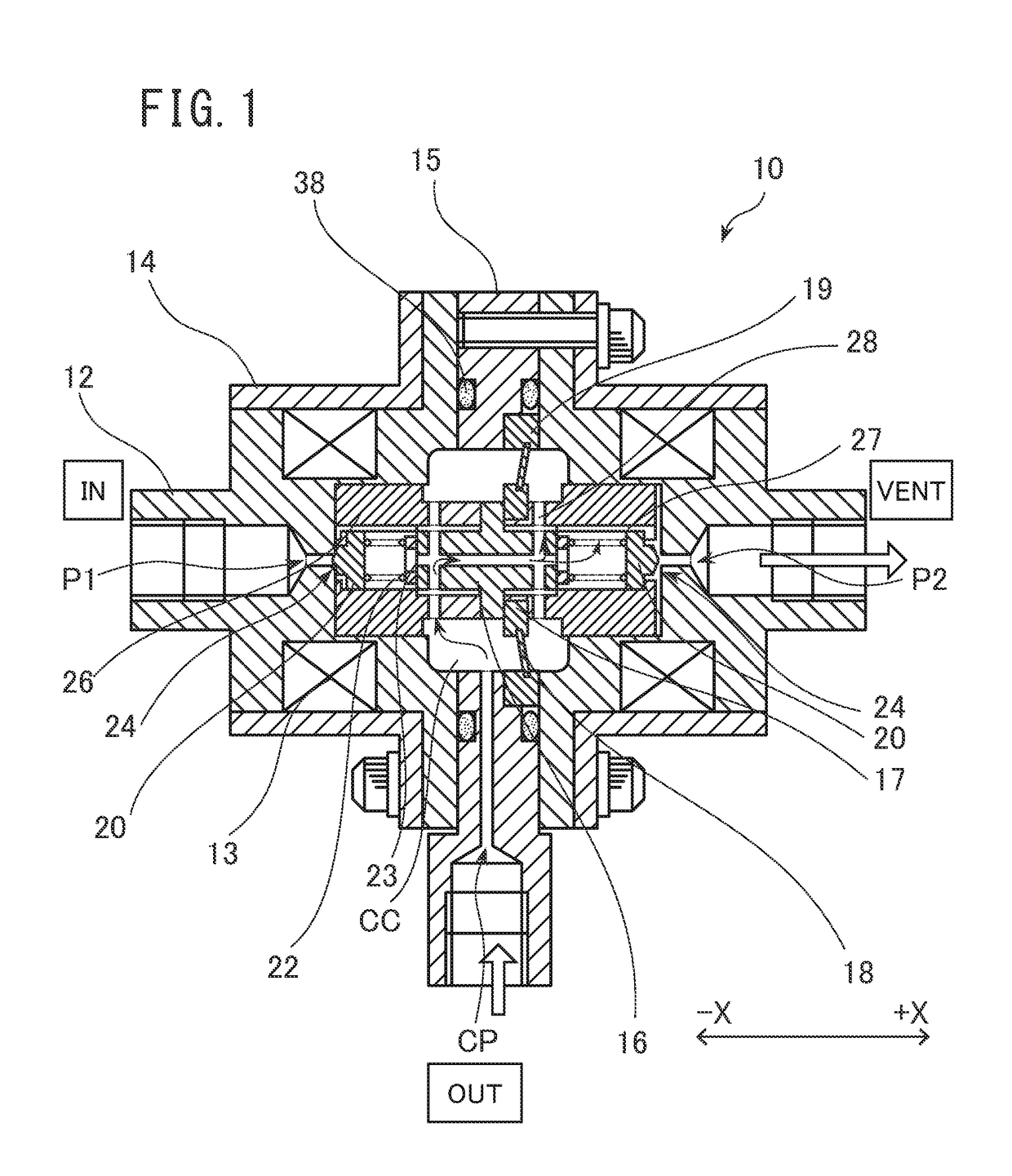
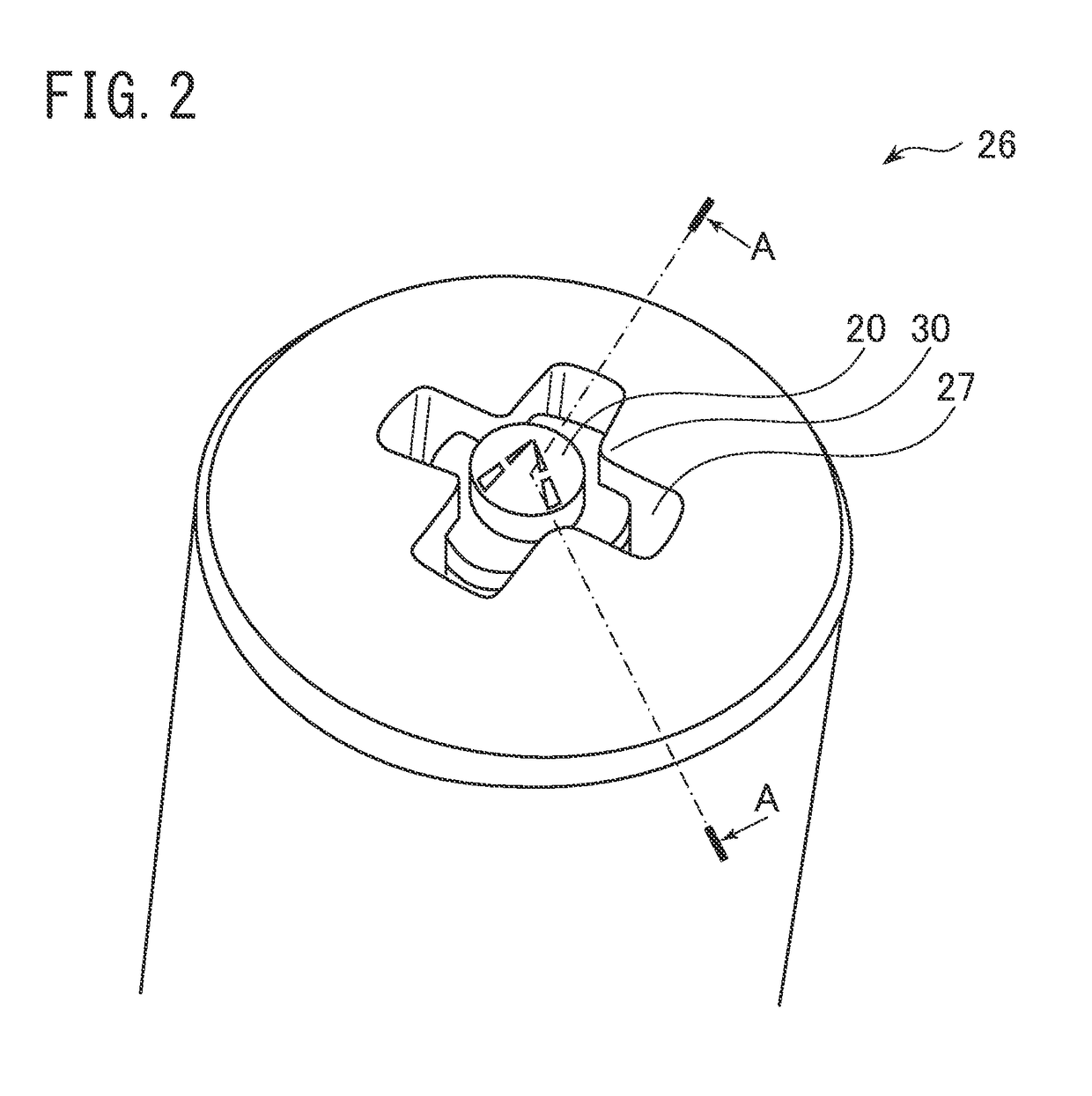
[0035]FIG. 1 is the cross-sectional view for illustrating the configuration example of the three-port double-latch type electromagnetic valve in the first keeping state to which the switching valve of some embodiment is applied. FIG. 2 is the external perspective view of the end face portion of the sliding core to be used for the switching valve of some embodiment. FIG. 1 is the cross-sectional view taken along line A-A in FIG. 2 when viewed from the direction indicated by the arrows.

[0036]The switching valve 10 shown in FIG. 1 and FIG. 2 is a three-port type valve with which it is possible to control cryogenic fluid such as liquid oxygen and liquid hydrogen, or control high-temperature fluid up to about 200 degrees Celsius. These three ports are, hereinafter, referred to as a first end port P1, a s...


PUM


Abstract

A switching valve has a cylinder, an end port, a side wall port, a sliding core, a poppet seal, a biasing member, and a sliding core internal channel. The cylinder guides the sliding core in a slidable manner, and has a valve seat. The poppet seal guided in a slidable manner in a sliding core inner space is biased toward a seal engagement protrusion by the biasing member. The poppet seal can be seated on the valve seat by a biasing force given by the biasing member to close a channel for controlled fluid, and can be separated from the valve seat to open the channel for the controlled fluid.

Description

TECHNICAL FIELD[0001]The present invention relates to a switching valve that has high reliability even in environments which are not at room temperature, has superior durability, is compact, and has low power consumption.BACKGROUND ART[0002]In JP 2000-016099 A (Patent Literature 1), an invention related to a poppet type check valve arranged at a lower end of a filler pipe of a vehicle fuel tank is disclosed. The invention of the check valve disclosed in Patent Literature 1 has a valve seat portion having tapered inner surface and a seal member disposed on a peripheral portion of a valve body. The invention has an object of mitigating an impact when the valve body collides with the valve seat portion.[0003]On a peripheral portion of the seal member of the check valve disclosed in Patent Literature 1, a lip portion made of elastic material such as NBR (Nitrile Butadiene Rubber: Nitrile rubber) is disposed. Thus, a configuration in which the lip portion is seated on the valve seat port...

Claims


Application Information

Patent Timeline
IPC IPC(8): F16K31/06H01F7/16H01F7/08F16K25/00H01F7/06
CPCF16K31/0627F16K31/0679H01F7/16H01F7/064H01F7/081F16K25/005F16K31/0606
Inventor AIHARA, HIROYUKIKONDO, AKIRA
Owner MITSUBISHI HEAVY IND LTD
Why Eureka
Try Eureka