Touch panel

Active Publication Date: 2017-04-06
MURATA MFG CO LTD
View PDF3 Cites 6 Cited by
  • Summary
  • Abstract
  • Description
  • Claims
  • Application Information

AI Technical Summary

Benefits of technology

[0023]As for ultraviolet ray irradiation, it is possible to lower the modulus by lowering a molecular weight of polymer used for the adhesive. Further, as for heat ray irradiation, if the adhesive contains thermosetting resin such as epoxy resin, the adhesive thermally cures, so that it is possible to increase the modulus. In addition, as for thermal curing, it is possible to increase the modulus at a higher speed by using dielectric heating caused by microwave irradiation. As for radiation irradiation, a radiation crosslinking effect re-couples molecules, and a molecular weight increases, so that it is possible to enhance the modulus. The modulus can be increased in this way by containing triallyl isocyanura

Problems solved by technology

Therefore, it is not possible to detect voltages corresponding to the distortions of the piezoelectric films.
Therefore, it is not possible to appropriately detect a pressing force from a pressing position at which the distortion amounts of the pi

Method used


Image

  • Touch panel
  • Touch panel
  • Touch panel

Examples


Example

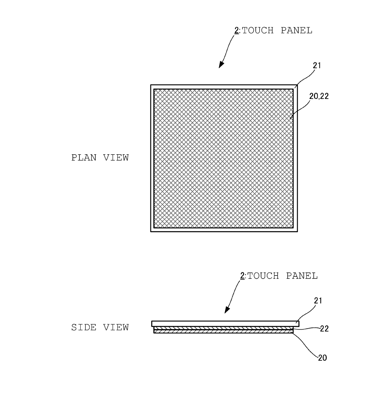
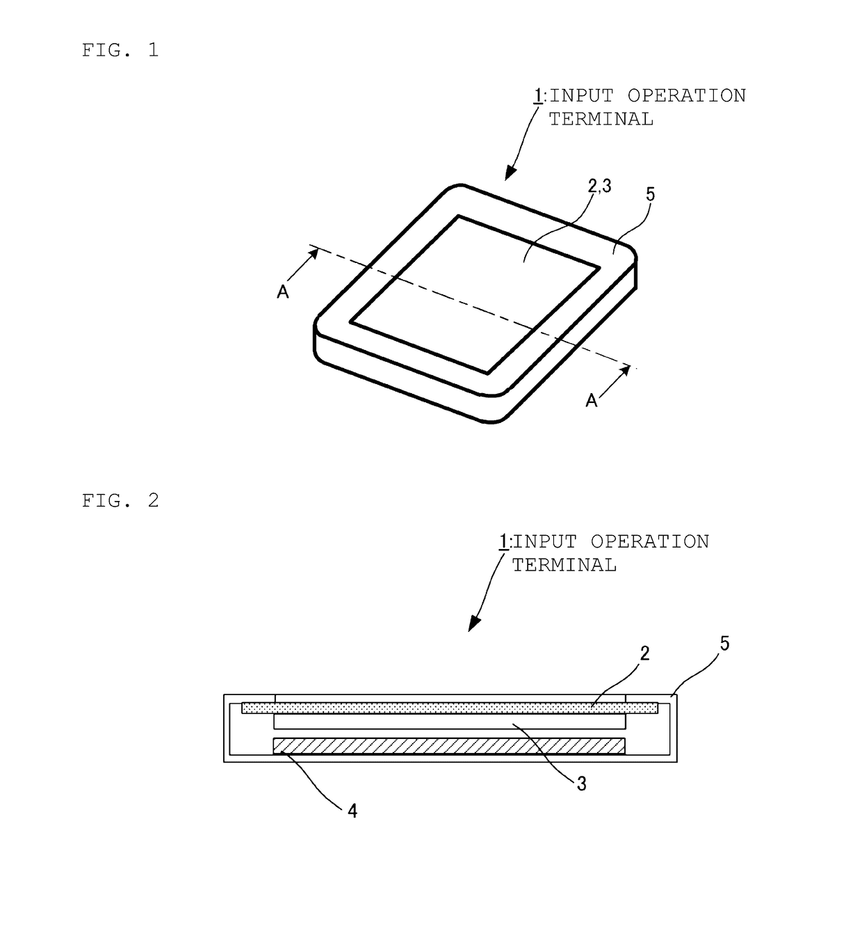
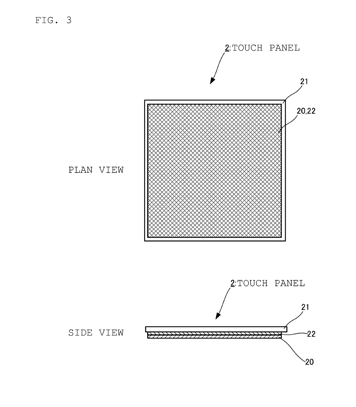
[0042]A touch panel according to an embodiment of the present invention will be described below. FIG. 1 is a schematic view illustrating an external appearance of an input operation terminal including a touch panel according to the embodiment. FIG. 2 is a sectional view taken along a direction A-A illustrated in FIG. 1. An input operation terminal 1 according to the present embodiment employs a configuration where a touch panel 2, an indicator 3 and a control substrate 4 are attached in a housing 5. The housing 5 has a nearly cuboid shape as illustrated in FIG. 1. The housing 5 has a shape whose upper surface in FIG. 1 includes an opening surface of a rectangular shape. In the present embodiment, this opening surface is nearly square.

[0043]The touch panel 2 is attached such that a first principal surface described below blocks the opening surface of the rectangular shape formed in the upper surface of housing 5. That is, the first principal surface is exposed through the opening sur...


PUM

PropertyMeasurementUnit
Thicknessaaaaaaaaaa
Piezoelectricityaaaaaaaaaa
Modulusaaaaaaaaaa

Abstract

A touch panel that includes a plate member which includes a first principal surface and a second principal surface opposing each other, and is constructed so as to be distorted in response to a force applied to the first principal surface; a main functional unit having piezoelectric voltage detection electrodes disposed on opposed sides of a piezoelectric film and which detect a piezoelectric voltage corresponding to a distortion amount of the piezoelectric film; and an adhesive layer which adheres the plate member and the main functional unit, the adhesive layer being divided into a plurality of areas, and at least two areas have different moduli.

Description

CROSS REFERENCE TO RELATED APPLICATIONS[0001]The present application is a continuation of International application No. PCT / JP2015 / 066810, filed Jun. 11, 2015, which claims priority to Japanese Patent Application No. 2014-136714, filed Jul. 2, 2014, the entire contents of each of which are incorporated herein by reference.FIELD OF THE INVENTION[0002]The present invention relates to a touch panel which detects a pressing operation of an operator with respect to an operation surface.BACKGROUND OF THE INVENTION[0003]Conventionally, touch panels which each simultaneously detect a touch position and a push amount (pressing force) of a touch when an operator touches an operation surface of a planar shape by a finger or the like have been proposed.[0004]For example, Patent Document 1 discloses a thin touch panel which simultaneously detects a touch position and a push amount by disposing capacitance detection electrodes on at least one of a side of a first principal surface and a side of a...

Claims


Application Information

Patent Timeline
IPC IPC(8): G06F3/044B32B7/12
CPCG06F3/044B32B7/12B32B2457/208G06F2203/04105G06F2203/04103B32B25/08B32B25/12B32B25/20B32B27/08B32B27/18B32B27/283B32B27/308B32B27/32B32B27/36B32B27/365B32B2250/44B32B2307/20B32B2307/412B32B2307/516B32B2307/704B32B2307/732G06F3/0445G06F3/0446G06F2203/04106
Inventor ANDO, MASAMICHIMORI, KENICHI
Owner MURATA MFG CO LTD
Why Eureka
Try Eureka