
Measuring device, measuring system, measuring method, and program

a technology of measuring devices and sensors, applied in the field of measuring devices, can solve the problems of increasing the scale of the measuring system, affecting the accuracy of the measurement results, and affecting the accuracy of the measurement results, and achieve the effect of simple procedur

Active Publication Date: 2017-04-06
SEIKO EPSON CORP
View PDF4 Cites 19 Cited by
  • Summary
  • Abstract
  • Description
  • Claims
  • Application Information

AI Technical Summary

Benefits of technology

The invention provides a system for acquiring information about a moving object, such as a vehicle, on a structure, like a bridge. This is done using a small-scale and simple system configuration. The system includes an acceleration sensor on the structure that measures the width direction acceleration of the road surface on which the moving object moves. This data is then used to acquire information about the moving object, such as its speed and direction of movement. This invention helps to gather valuable information about moving objects on structures, which can aid in various applications, such as improving transportation infrastructure and ensuring safety.

Problems solved by technology

However, in JP-A-2005-30786, a large number of various types of sensors are used, which leads to an increase in the scale of a measuring system.
For this reason, a large amount of labor and cost are incurred in the installation or maintenance of these sensors.
In addition, in JP-A-2005-30786, since a large number of sensors are used, it is necessary to process vast amounts of data, and thus the process of a computer becomes complicated, or a processing load increases.

Method used


Image

  • Measuring device, measuring system, measuring method, and program
  • Measuring device, measuring system, measuring method, and program
  • Measuring device, measuring system, measuring method, and program

Examples


first embodiment

[0044

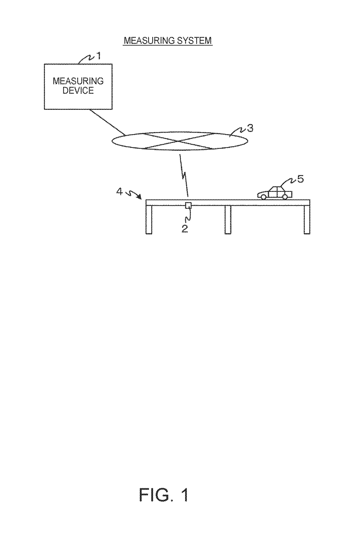
[0045]FIG. 1 is a diagram illustrating an example of a schematic configuration of a measuring system according to a first embodiment of the invention.

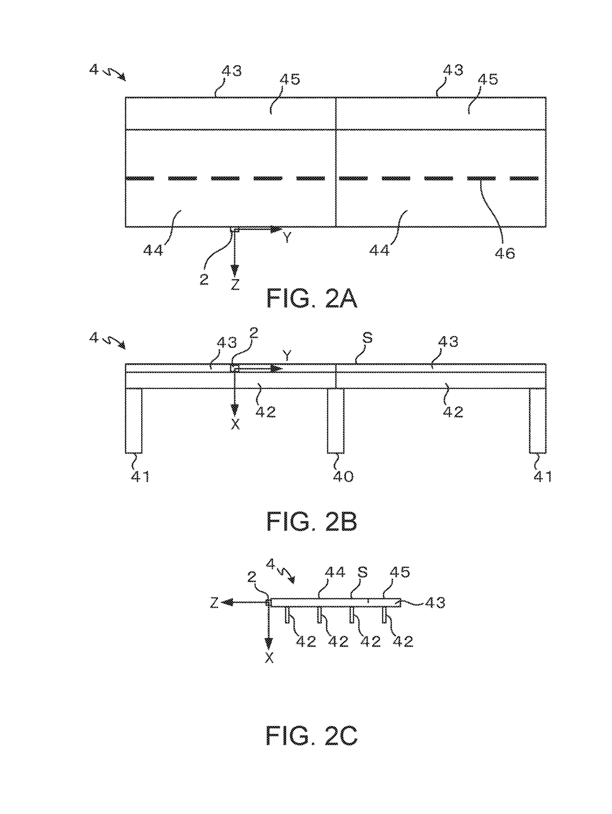
[0046]The measuring system includes a measuring device 1 and an acceleration sensor 2. The measuring device 1 and the acceleration sensor 2 are communicably connected to each other through a communication network 3. The acceleration sensor 2, installed on a bridge 4, measures acceleration generated in the bridge 4 by the passage of a vehicle 5 or the like, and transmits measurement data to the measuring device 1. The measuring device 1 receives the measurement data from the acceleration sensor 2, and acquires information (position, weight or the like) relating to the vehicle 5, using acceleration included in the measurement data.

[0047]Meanwhile, the acceleration sensor 2 has, for example, a wireless communication interface, or is connected to a wireless communication interface, and is connected to the communication network 3 throu...

second embodiment

[0119

[0120]In the first embodiment, the characteristic information indicating a relationship between the scale and the weight is stored in the storage unit 13 in advance. In this case, since the characteristic information is not able to be corrected, it is not possible to improve the accuracy of the determination of the weight of the vehicle 5. Consequently, in second embodiment, components for calibrating the characteristic information are provided. Hereinafter, the same components as those in the first embodiment are denoted by the same reference numerals and signs, and thus the description thereof will not be given. A description will be given with a focus on different components.

[0121]FIG. 14 is a diagram illustrating an example of a schematic configuration of a measuring system according to a second embodiment of the invention.

[0122]The measuring system includes a camera 6. The measuring device 1 and the camera 6 are communicably connected to each other through the communicatio...


PUM


Abstract

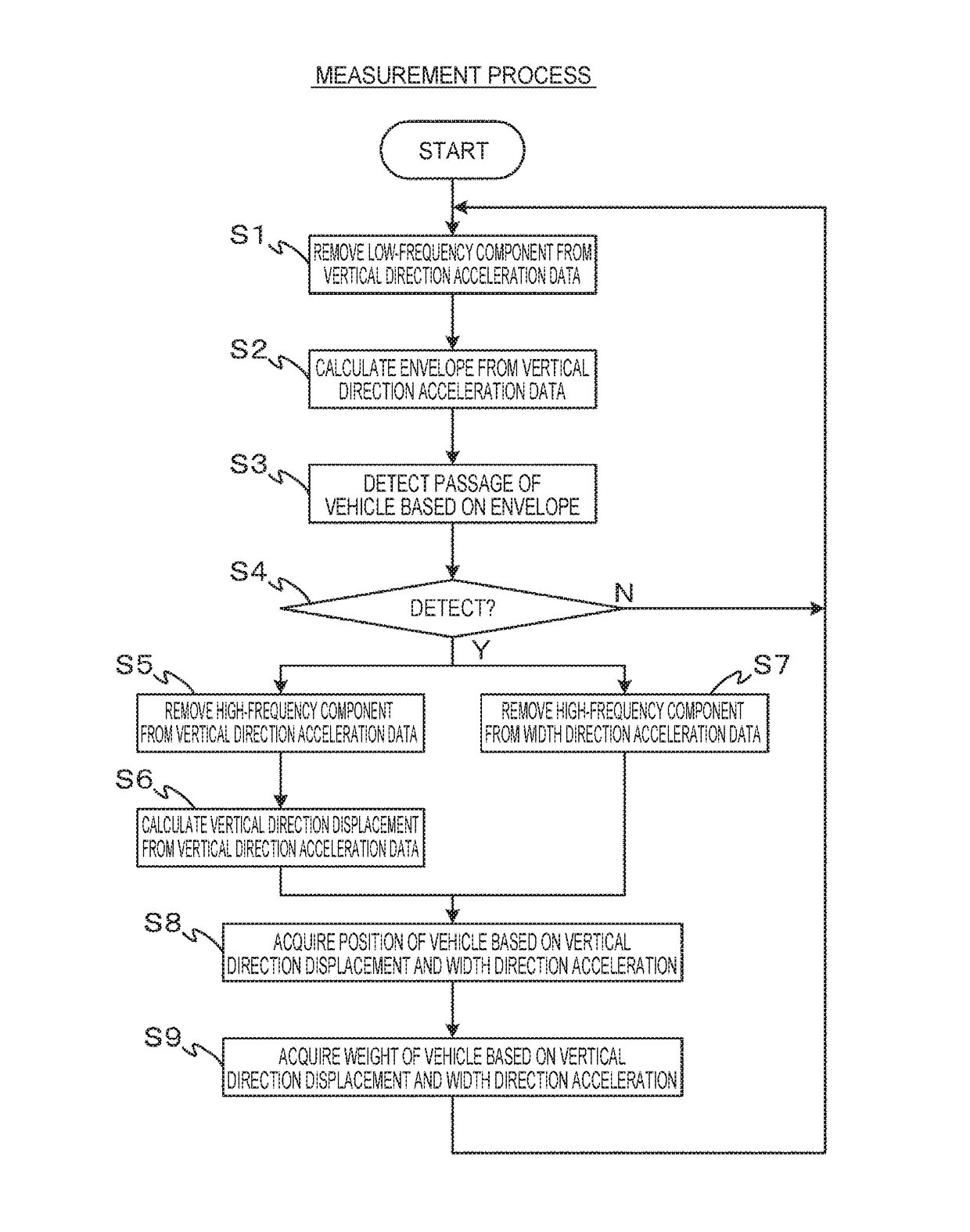
A measuring device includes a data acquisition unit that acquires measurement data, including width direction acceleration of a road surface on which a moving object moves, from an acceleration sensor provided on a structure having the road surface, and a moving object information acquisition unit that acquires information relating to the moving object moving on the road surface, on the basis of the width direction acceleration.

Description

BACKGROUND[0001]1. Technical Field[0002]The present invention relates to a measuring device, a measuring system, a measuring method, and a program.[0003]2. Related Art[0004]JP-A-2005-30786 discloses that a bridge is provided with a plurality of sensors for speed detection, a plurality of sensors for wheel axle detection, a distance sensor for vehicle position detection, and a plurality of strain gauges, and the speeds, positions, number, weights and the like of vehicles traveling on the bridge are calculated using signals from these devices.[0005]However, in JP-A-2005-30786, a large number of various types of sensors are used, which leads to an increase in the scale of a measuring system. For this reason, a large amount of labor and cost are incurred in the installation or maintenance of these sensors. In addition, in JP-A-2005-30786, since a large number of sensors are used, it is necessary to process vast amounts of data, and thus the process of a computer becomes complicated, or ...

Claims


Application Information

Patent Timeline
Patent Type & Authority Applications(United States)
IPC IPC(8): G06K9/00G01G23/01G01B7/00B60R11/04G06T7/20G06T7/60G06K9/52G01G19/03G06T7/00
CPCG06K9/00791G01G19/035G01G23/01G01B7/003G06T7/004G06T2207/30252G06K9/00335G06T7/60G06K9/52B60R11/04G06T7/20G01P15/00G01M5/0008G01P1/127G06V20/58G06V10/431G06V10/809G06F18/254G06V20/56G06V40/20
Inventor KOBAYASHI, YOSHIHIRO
Owner SEIKO EPSON CORP
Learn More