Power converter and method for manufacturing the same

Active Publication Date: 2017-04-13
DELTA ELECTRONICS INC
View PDF4 Cites 3 Cited by
  • Summary
  • Abstract
  • Description
  • Claims
  • Application Information

AI Technical Summary

Benefits of technology

[0013]Therefore, in view of the foregoing, embodiments of the present disclosure provide a power converter and a method for manufacturing the same t

Problems solved by technology

If wide application range is considered for designing the pins, the size of the power converter is larger, the cost is higher, and the power consumption is greater.
In view of

Method used


Image

  • Power converter and method for manufacturing the same
  • Power converter and method for manufacturing the same
  • Power converter and method for manufacturing the same

Examples


Embodiment Construction

[0041]The detailed description provided below in connection with the appended drawings is intended as a description of the present examples and is not intended to represent the only forms in which the present example may be constructed or utilized. The description sets forth the functions of the example and the sequence of steps for constructing and operating the example. However, the same or equivalent functions and sequences may be accomplished by different examples.

[0042]Unless otherwise defined herein, scientific and technical terminologies employed in the present disclosure shall have the meanings that are commonly understood and used by one of ordinary skill in the art.

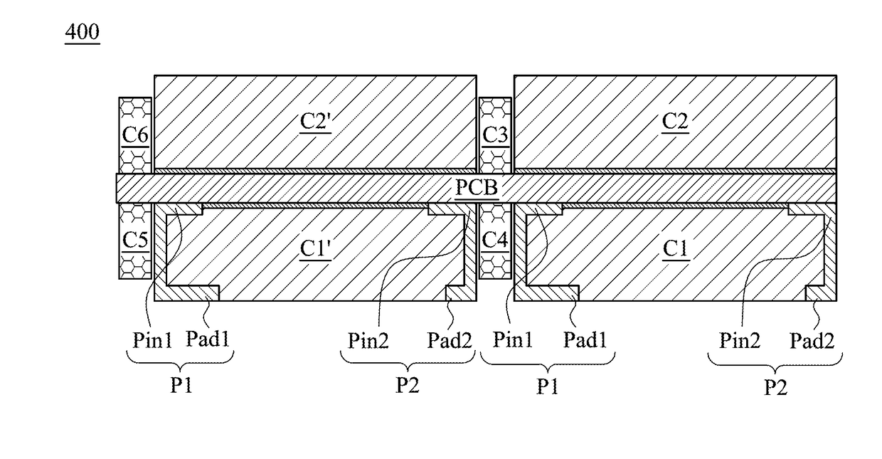
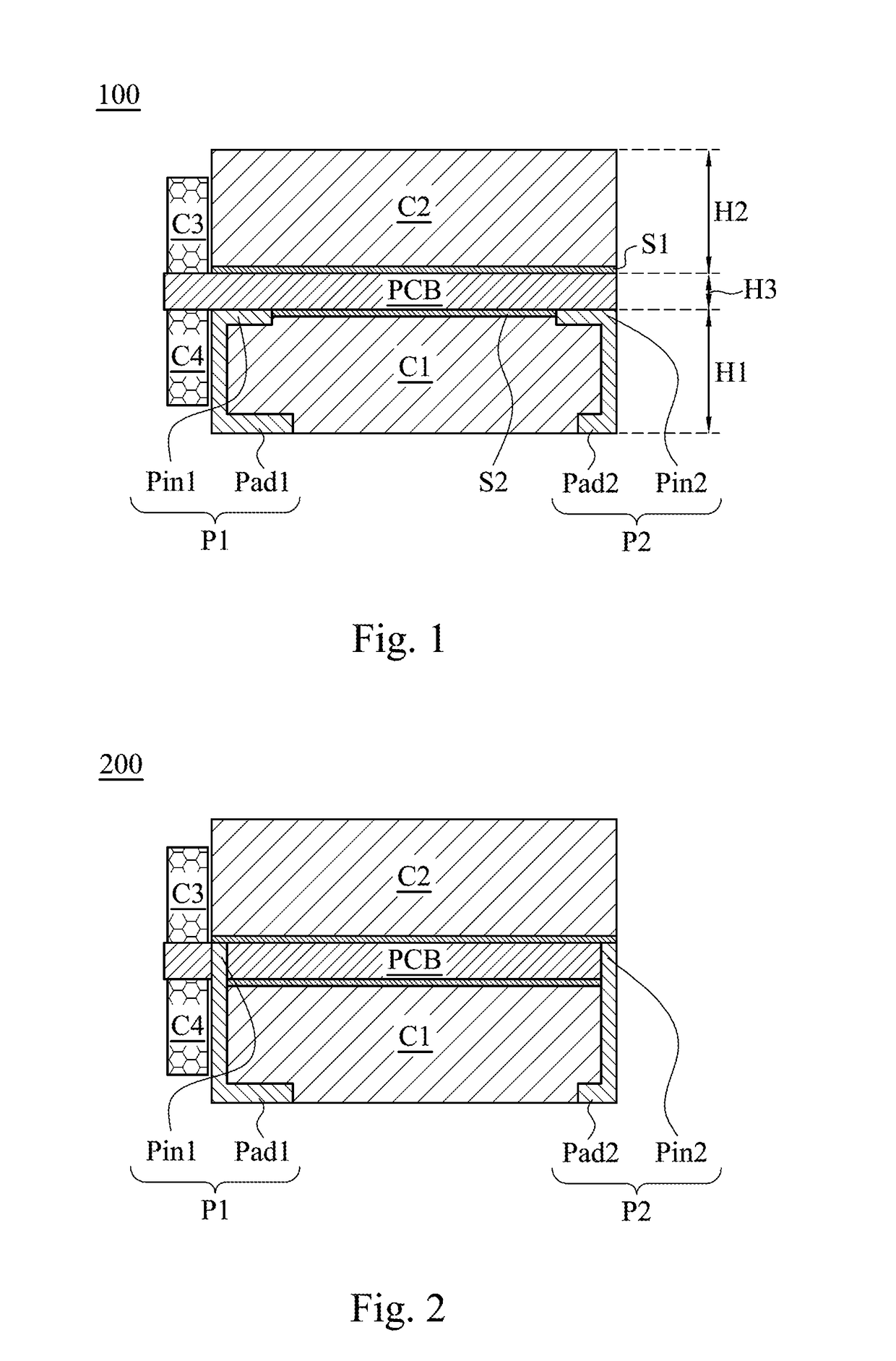
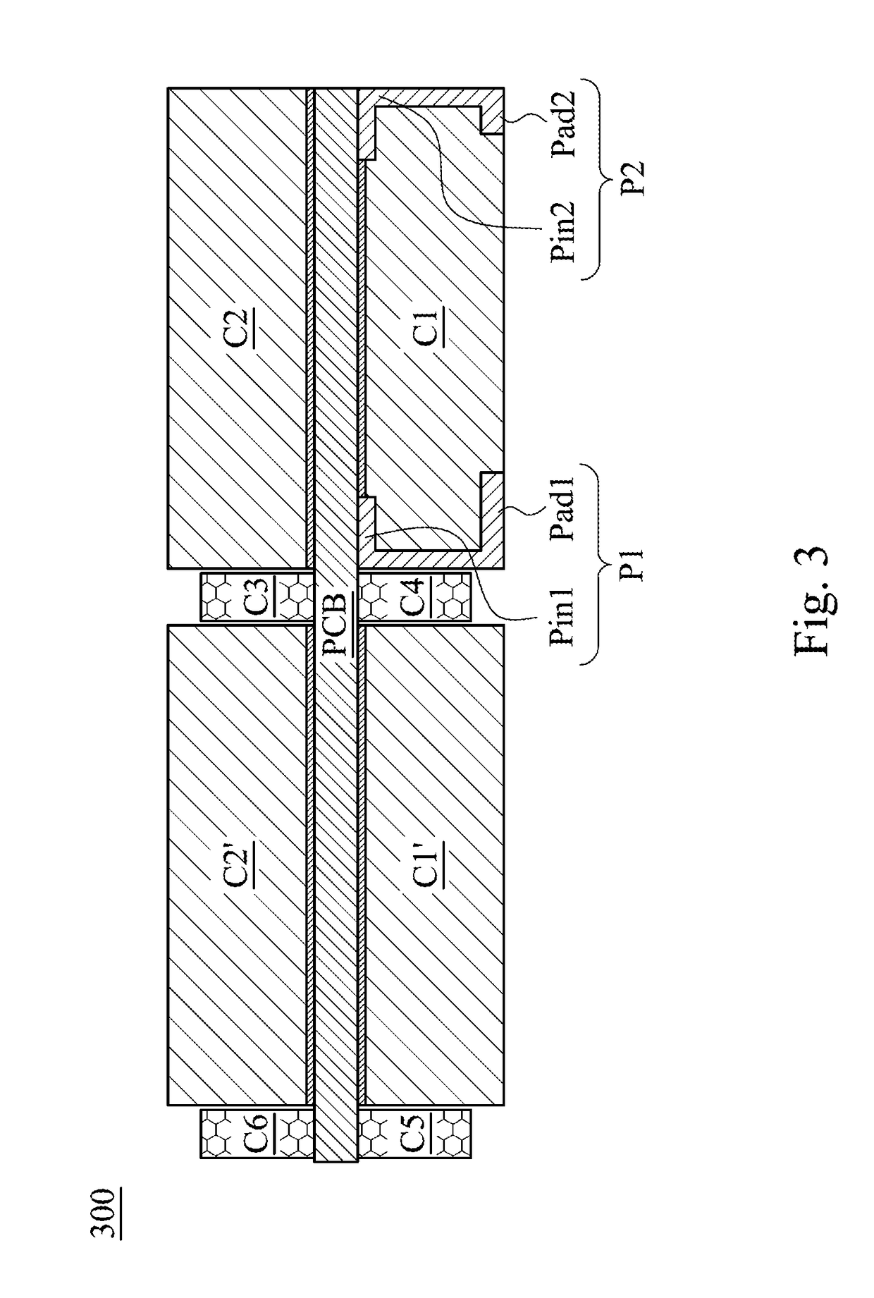
[0043]FIG. 1 illustrates a schematic diagram of a power converter in accordance with embodiments of the present disclosure. As shown in FIG. 1, the power converter 100 includes a carrier PCB, a first electronic component C1, a second electronic component C2, a first connection part P1 and a second connection par...


PUM


Abstract

A power converter includes a carrier, a first electronic component, a second electronic component, and a connection part. The first electronic component is disposed on the bottom surface of the carrier. The second electronic component is disposed on the top surface of the carrier. A first terminal of the connection part is coupled to the top surface or the bottom surface of the carrier. A second terminal of the connection part is a bonding pad and attached to the first electronic component's surface apart from the carrier. The carrier is disposed at ⅓ to ⅔ of a height of the power-converter. The connection part is fabricated by mechanical support of the first electronic component.

Description

RELATED APPLICATIONS[0001]This application claims priority to Chinese Patent Application No. 201510648280.1, filed on Oct. 9, 2015, which is herein incorporated by reference.BACKGROUND[0002]Field of Disclosure[0003]The present disclosure relates to a power converting technology, and more particularly, to a power converter and a method for manufacturing the same.[0004]Description of Related Art[0005]With the development of smart life technology, demands for data processing have been increased. The averaged energy consumption for data processing throughout the world achieves hundreds of billions of kilowatt-hours or even trillions of kilowatt-hours per year. Furthermore, a large data center is often has an occupied area up to ten thousands of square meters. Therefore, high efficiency and high power density are key factors for sustainable development of industry.[0006]The key to the function of the data center is a server, where the motherboard usually consists of data processing chips...

Claims


Application Information

Patent Timeline
IPC IPC(8): H02M3/156H05K1/02H05K1/18H05K3/22H01F27/24H05K3/30H05K3/40H05K1/11H01F27/28
CPCH02M3/156H05K1/111H05K1/028H05K1/181H01F27/28H05K2203/02H05K3/305H05K3/4038H05K3/22H05K2201/1003H05K2203/0228H01F27/24H01L23/49575H01L25/16H02M1/00H05K1/145H05K1/147H05K1/18H05K2201/10946H01F27/292H01F41/02
Inventor ZENG, JIAN-HONGHONG, SHOU-YUXIN, XIAO-NIHU, PEI-QING
Owner DELTA ELECTRONICS INC
Why Eureka
Try Eureka